

Vacuum hose handling and safety vacuum release system
a technology of vacuum hose and release system, which is applied in the installation of electric equipment, cleaning equipment, mechanical machines/dredgers, etc., can solve the problems of many fatalities, slow blue stake response, and many safety problems
- Summary
- Abstract
- Description
- Claims
- Application Information
AI Technical Summary
Benefits of technology
Problems solved by technology
Method used
Image


Examples
Embodiment Construction
[0029]As discussed above, embodiments of the present invention relate to an industrial vacuum nozzle device and more particularly to a vacuum hose handling and safety vacuum release system as used to improve the safety and efficiency of operating such a device.
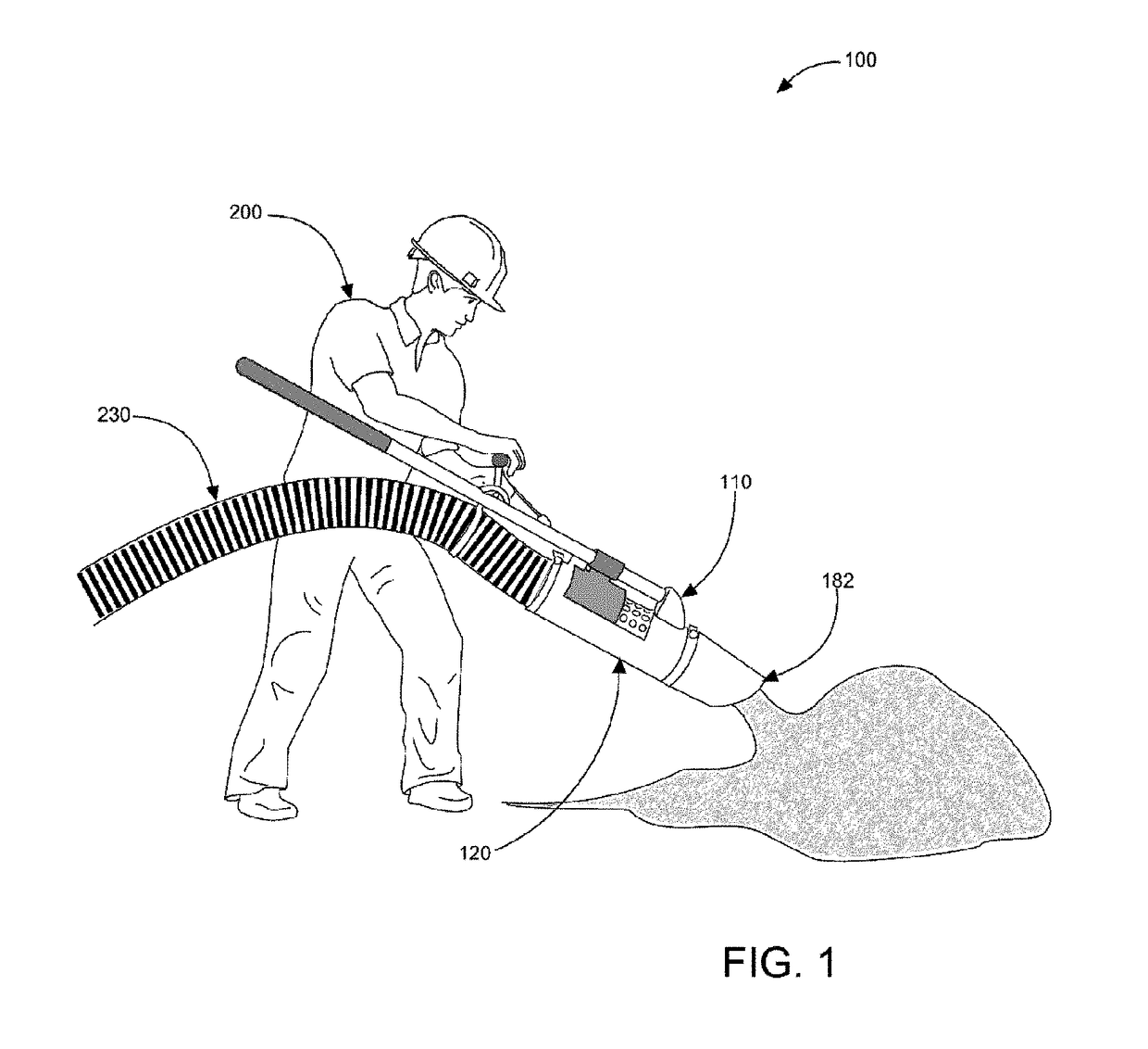
[0030]In greater detail now, referring to the drawings by numerals of reference there is shown in FIG. 1, a perspective view illustrating an in-use condition of vacuum hose handling and safety vacuum release system 100 according to an embodiment of the present invention.
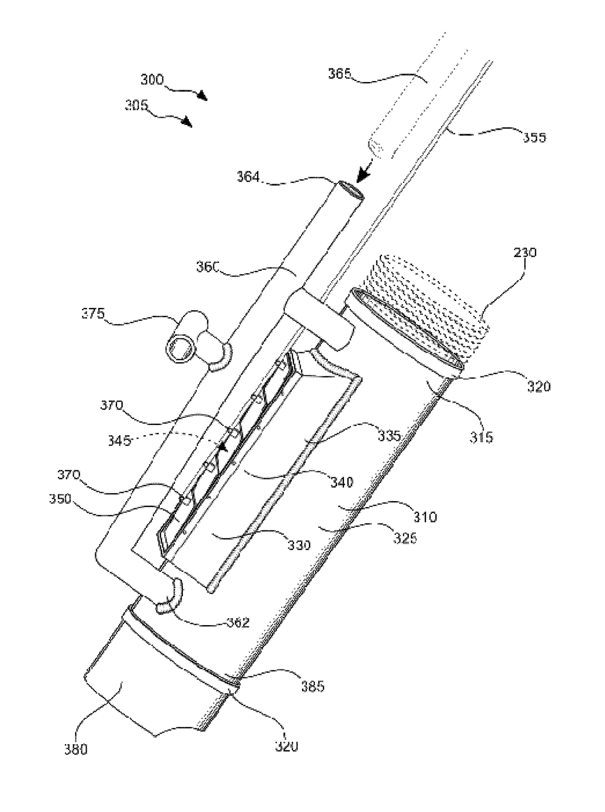
[0031]Vacuum hose handling and safety vacuum release system 100 comprises vacuum hose handling assembly 110 having column 120 (having proximate end 122 and distal end 124), at least one handle 130 (having first end 132 having grip 140, and second end 134), vacuum release lever 150, vacuum release linkage 160, vacuum release orifice stopper 170, removable suction end 180, and suction end securer band 190. Vacuum hose handling assembly 110 is useful for controlla...
PUM
 Abstract
Description
Claims
Application Information