System for influencing exhaust noise in a multi-flow exhaust system

a multi-flow exhaust and system technology, applied in the direction of electrical transducers, machines/engines, mechanical equipment, etc., can solve the problems of low noise, low cost, and inability to naturally generate the characteristic noise of the engine (or motor) that is not attractive to users, etc., to achieve low cost and low complexity

Active Publication Date: 2017-07-11
PUREM GMBH
View PDF39 Cites 4 Cited by
  • Summary
  • Abstract
  • Description
  • Claims
  • Application Information

AI Technical Summary

Benefits of technology

[0017]Embodiments of the present invention provide an anti-noise system for influencing exhaust gas noises propagating through multi-flow exhaust systems, the anti-noise system being of low complexity and low cost.
[0019]As a consequence, the sound generator is assigned to at least two exhaust tracts of the multi-flow exhaust system simultaneously and fills them with sound via a fluid connection. In a multi-flow exhaust system it is therefore not necessary to provide a separate sound generator with at least one actuator for each of the exhaust tracts. Accordingly, only one controller is required. This saves installation space and cost, and reduces the complexity of the construction.
[0023]The error microphone is thus associated with at least two exhaust tracts of the multi-flow exhaust system simultaneously so that only one closed-loop control circuit is required. This reduces the complexity of the construction.
[0038]According to an embodiment, the lengths of all of the at least two exhaust tracts of the multi-flow exhaust system between the internal combustion engine and the position along the respective exhaust tract, at which the sound generator is connected to the respective exhaust tract, are identical. Alternatively, differences in length of less than 10%, and in particular of less than 5%, and further in particular of less than 3% are allowed. Further, also the lengths of the respective conduits between a respective exhaust tract and the sound generator is identical. Alternatively, differences in length of less than 10%, and in particular of less than 5%, and further in particular of less than 3% are allowed. Differences in the time required for sound to propagate through the exhaust tracts due to different lengths of the conduits are hereby prevented.

Problems solved by technology

These noises are often regarded as being disadvantageous.
Present-day engines with small displacement often cannot naturally generate such intended characteristic noise.
With the increasing use of internal combustion engines having small displacements or even of electric motors, the problem arises that the engine (or motor) noise is often not attractive for users and / or does not fit the image of a vehicle manufacturer.
The disadvantage of both operating principles is that they require a comparatively large volume and create a comparatively high resistance to the combusted fuel-air mixture resulting in a drop of the vehicle's overall efficiency and an increased fuel consumption.
It is a disadvantage of already known systems for influencing exhaust noise that these systems are not designed for multi-flow exhaust systems.

Method used


Image

  • System for influencing exhaust noise in a multi-flow exhaust system
  • System for influencing exhaust noise in a multi-flow exhaust system
  • System for influencing exhaust noise in a multi-flow exhaust system

Examples


Embodiment Construction

[0060]Hereinafter, several embodiments of the present invention are explained with respect to the Figures.

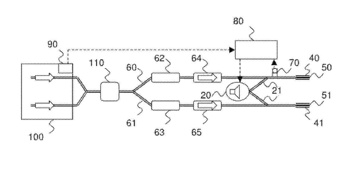
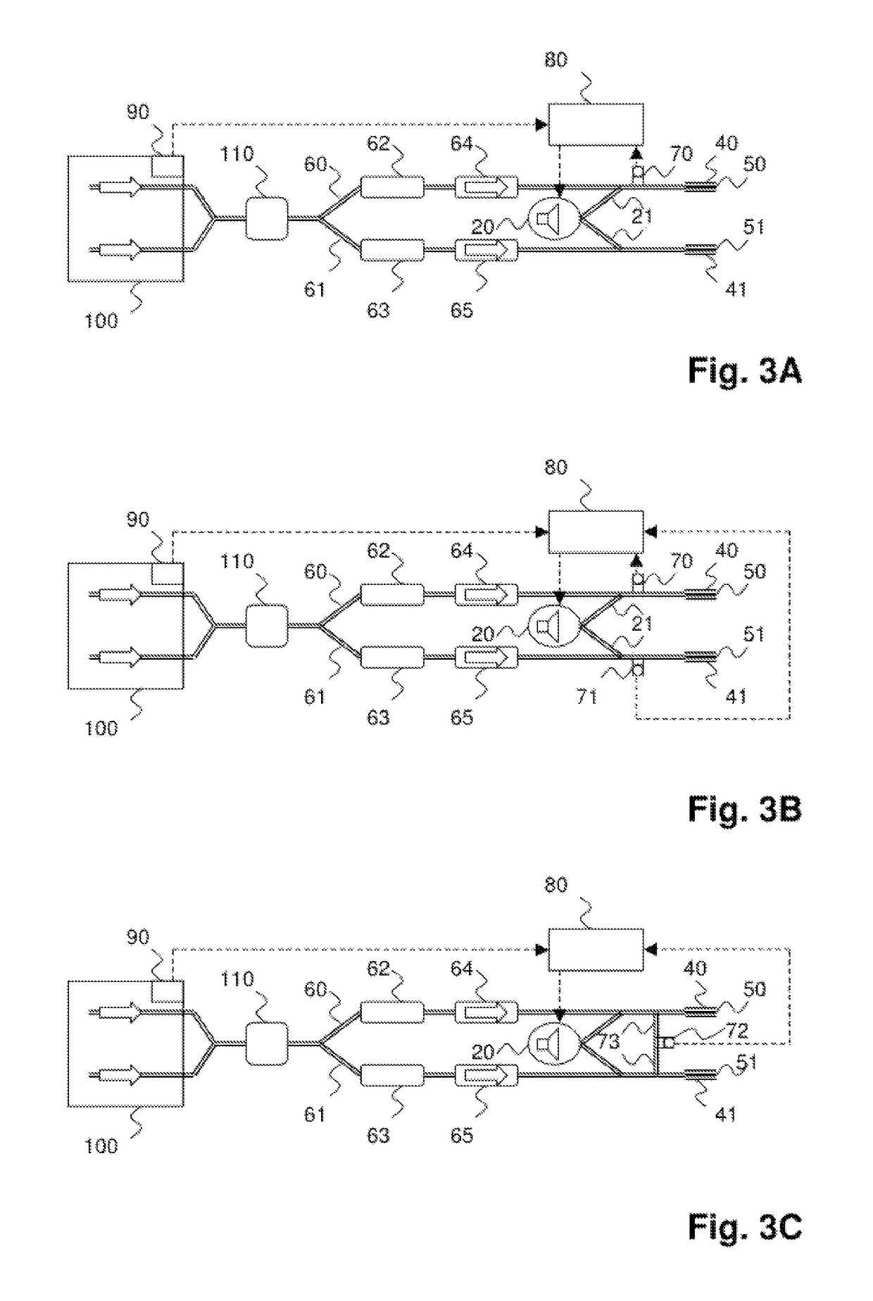
[0061]Referencing FIGS. 3A, 3B, 3C, the exhaust gas streams generated by an internal combustion engine 100 are first combined and then supplied to a turbocharger 110. Afterwards, the exhaust gas is separately passed along two exhaust tracts 60, 61 through two catalytic converters 62, 63 and two premufflers 64, 65, and finally discharged to the surroundings through discharge openings 50, 51 of tail pipes 40, 41. The direction of flow of the exhaust gas is indicated by arrows.

[0062]It is noted that the turbocharger 110, the catalytic converters 62, 63, and the premufflers 64, 65 are only optional. Alternatively or additionally, other elements may also be provided for emission control and sound absorption. It is further noted that there may be more than one pair of exhaust tracts.

[0063]According to the embodiments of all FIGS. 3A, 3B, and 3C, the anti-noise system comprises a sound...


PUM


Abstract

An anti-noise system for influencing exhaust noises propagating through a multi-flow exhaust system includes a controller 80 and at least one actuator. The at least one actuator is disposed in a sound generator 20; 21; 23; 25; 27, connected to the controller 80 for receiving control signals, and adapted to generate sound inside the sound generator 20; 21; 23; 25; 27. The sound generator 20; 21; 23; 25; 27 is connectable to at least two exhaust tracts 60, 61 of the multi-flow exhaust system of the vehicle simultaneously. The controller 80 is configured to generate a control signal that prompts the at least one actuator disposed in the sound generator 20; 21; 23; 25; 27 to cancel sound inside the at least two exhaust tracts 60, 61 of the vehicle's multi-flow exhaust system at least in part and preferably completely.

Description

CROSS REFERENCE TO RELATED APPLICATIONS[0001]The present application claims priority of German Patent Application DE 10 2013 010 609.5, filed Jun. 25, 2013 in Germany, the entire contents of which are incorporated by reference herein.FIELD OF THE INVENTION[0002]The invention relates to a system for influencing sound waves propagating through exhaust systems of vehicles driven by internal combustion engines (exhaust noises). More specifically, the present invention relates to a system for influencing the sound waves propagating through multi-flow exhaust systems.BACKGROUND OF THE INVENTION[0003]Multi-flow exhaust systems are used for reliably discharging high volume exhaust gas flows with little resistance. High volume exhaust gas flows occur in particular with powerful engines. It is characteristic for multi-flow exhaust systems that exhaust gas from the internal combustion engine and exhaust gas passing through the exhaust system is discharged into the surroundings via at least two...

Claims


Application Information

Patent Timeline
Patent Type & Authority Patents(United States)
IPC IPC(8): H04R3/00F01N1/06F01N13/04F01N13/00
CPCH04R3/002F01N1/06F01N1/065F01N13/011F01N13/04
Inventor POMMERER, MICHAELKOBE, JUERGENHOELSCH, RALFWINK, PETER
Owner PUREM GMBH
Why Eureka
Try Eureka