Microwave contactless heart rate sensor

a heart rate sensor and microwave technology, applied in the field of contactless heart rate sensors, can solve the problems of inconvenient wearing of the chest strap associated with this type of collar strap, intermittent pulse rate measurement, and too week-long reception of ecg signal

Active Publication Date: 2017-07-25
SENSIFREE
View PDF30 Cites 11 Cited by
  • Summary
  • Abstract
  • Description
  • Claims
  • Application Information

AI Technical Summary

Benefits of technology

[0020]d) a window function circuitry (e.g., a Kaiser window with β=0.5, a Tukey Window or a window used in connection with Digital Fourier Transforms), for suppressing unwanted spectral sidebands originating from the subsequent processor operating on time truncated data;

Problems solved by technology

The chest strap associated with this type is inconvenient to wear.
Also, in some individuals, the ECG signal reception is too week, due to the varying body surface resistance.
This may result in intermittent pulse rate measurements.
However, for continuous pulse rate readout during training, it is impractical to use the beltless solution, as it requires the continuous connection of both hands.
However, this measurement is not sufficiently accurate, especially while in training.
However, both patents do not deal with the problem of separating the heart pulse rate measurement from other body organ movements.
Such movements frequency, in the case of sport training, fall within the normal heart rate frequency range and are not easy to filter out.
FFT for this application implies a long measurement time for reasonable accuracy, which cannot be tolerated in this type of application.
All the sensors described above have not provided a satisfactory solution to the problem of the problem of separating the heart pulse rate measurement from other body organ movements and are not sufficiently accurate.

Method used


Image

  • Microwave contactless heart rate sensor
  • Microwave contactless heart rate sensor
  • Microwave contactless heart rate sensor

Examples


Embodiment Construction

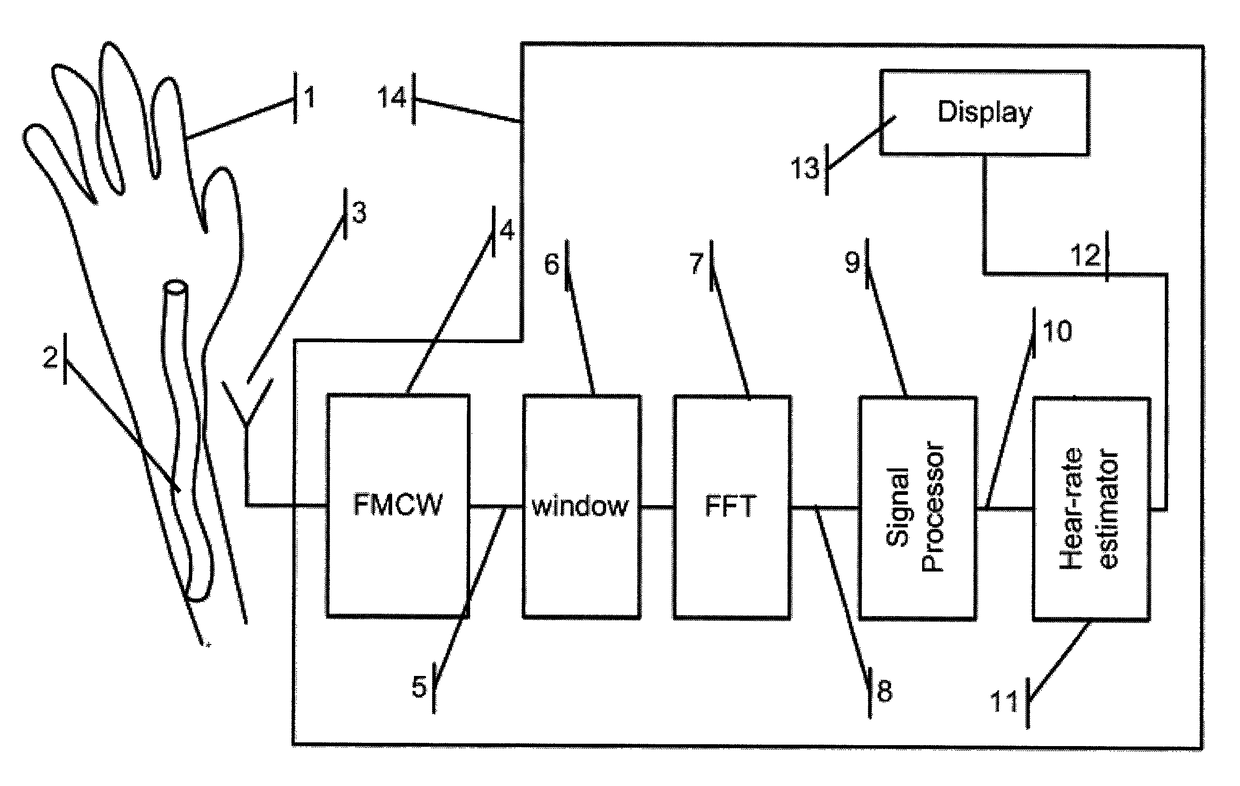
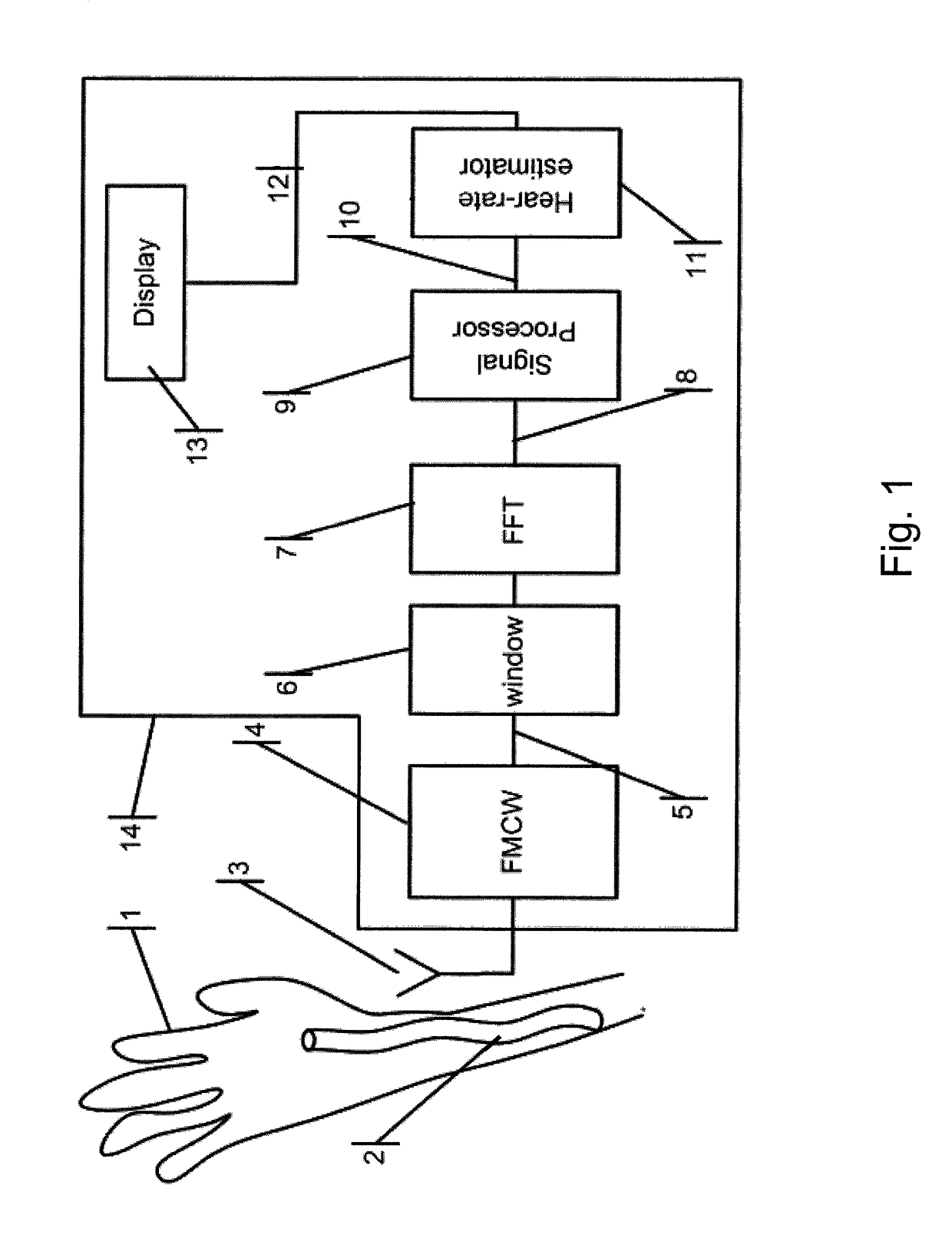
[0050]The sensor proposed by the present invention measures the variations in the blood volume flowing through the artery, by means of a microwave sensor, to produce a continuous reading of the heart-rate. The measurement is insensitive to rhythmic relative movement of the sensor and subject, making it suitable for performing accurate heart-rate measurements, while the user is in training.

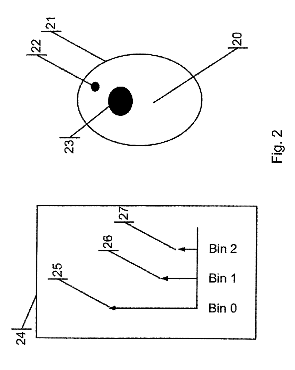
[0051]In a preferred embodiment, the measurement is performed on a human wrist, where the artery diameter varies by approximately 10% of its nominal value of approximately 2.5 mm during the pulse cycle.

[0052]The heart-rate sensor is located on a relevant body part, for example a limb above the artery to be measured. The proposed sensor transmits a microwave signal into the artery. The amplitude of the signal reflected from this artery depends on its instantaneous diameter, which in turn, represents the instantaneous blood pressure. Monitoring the rhythm or frequency of this reflection allows estima...


PUM


Abstract

A heart-rate sensor for detecting artery blood-flow volume per unit length change in a human or animal subject, which comprises an antenna for sensing the instantaneous volume of blood in the artery of the subject, to be measured; a RADAR unit for transmitting microwave signals into a subject's body part or limb representing tissue targets. The output of the RADAR unit includes a superposition of signals each of which corresponding to a different tissue target with amplitudes that relate to the target's reflection strength; a sampling circuitry for converting reflected signals to digital; a window function circuitry for suppressing unwanted spectral sidebands originating from the subsequent processor operating on time truncated data; an FFT processor following the window function circuitry, for splitting the superposition according to its relative frequency into a multiplicity of bins, each of which with an amplitude that represents the reflection magnitude of a target at a specific distance from the antenna; a signal processor for filtering out the effect of the sensor movement with respect to the subject body part, or the movement of the body part, and for generating a signal, the amplitude of which is proportional to the artery varying dilatation representing the heart-rate; a heart-rate estimator for measuring the frequency of the artery dilatation variations and for canceling the interference of the amplitude of any signal that does not originate from the artery; a battery for powering the sensor.

Description

RELATED APPLICATIONS[0001]The present application is a 371 National Stage Application of PCT application no. PCT / IL2013 / 050113, having an international filing date of Feb. 7, 2013, claiming priority to and benefit of U.S. provisional patent application No. 61 / 597,734, filed Feb. 11, 2012; both disclosures of which are herein incorporated by reference in their entiretiesFIELD OF THE INVENTION[0002]The present invention relates to the field of heart rate sensors. More particularly, the present invention relates to a contactless heart-rate sensor for continuously measuring of heart pulse rate of a human subject or an animal, by utilizing a low power compact microwave sensor.BACKGROUND OF THE INVENTION[0003]Conventional heart-rate sensors are embedded in monitors and are commonly used in training and sports. There are two common types of heart-rate sensors:[0004]The first type: is a monitor comprising a chest strap sensor and a receiver integrated into a wristwatch. The strap receives E...

Claims


Application Information

Patent Timeline
Patent Type & Authority Patents(United States)
IPC IPC(8): A61B5/05G01S13/88G01S13/58A61B5/00A61B5/026A61B5/024
CPCA61B5/0507A61B5/026A61B5/02444A61B5/681G01S13/583G01S13/88
Inventor BARAK, ILAN SAUL
Owner SENSIFREE
Why Eureka
Try Eureka