
System of preoperative planning and provision of patient-specific surgical aids

a preoperative planning and patient-specific technology, applied in the field of preoperative planning system, can solve the problems of difficult to palpate boney landmarks, may be difficult to implant,/b> may not enable desired shoulder function, and surgeons cannot always readily determine whether even a remodeled glenoid vault can be used

Active Publication Date: 2017-08-01
THE CLEVELAND CLINIC FOUND
View PDF565 Cites 16 Cited by
  • Summary
  • Abstract
  • Description
  • Claims
  • Application Information

AI Technical Summary

Benefits of technology

The present invention relates to a method and device for preoperative planning and provision of patient-specific surgical aids. This involves creating a virtual model of a patient's tissue and placing a virtual device in a predetermined position relative to the model. A patient-specific template is created with landmarks placed in a predetermined orientation. A physical placement guide is created based on the virtual placement guide and landmark orientation. The physical guide is used to position a surgical aid accurately during surgery. This invention allows for precise preoperative planning and improved surgical outcomes.

Problems solved by technology

The scapula 100 is also well padded with muscle, so that it may be difficult to palpate boney landmarks.
When the scapula has bone loss and / or significant pathology due to disease or trauma, the standard glenoid component 216 may be difficult to implant and / or may not enable desired shoulder function, if it cannot be implanted in a preferred manner.
However, the surgeon cannot always readily determine whether even a remodeled glenoid vault 110 will fit as desired with a standard prosthesis because the surgeon does not know how a “normal” glenoid vault 110 (for which the standard prosthesis is designed) should be shaped for that patient.
However, using a unique prosthesis design for each patient can result in future biomechanical problems resulting from a non-proven design and takes away the familiarity that the surgeon will likely have with standardized prosthesis designs.
Depending upon the patient's particular anatomy, the surgeon may not be able to precisely determine the location of the exposed area relative to the remaining, obscured portions of the bone through mere visual observation.
These factors, particularly in a minimally invasive surgical procedure, may make it difficult for the surgeon to orient the glenoid vault during surgery.
During surgery, and particularly minimally invasive procedures, the plane of the scapula may be difficult or impossible to determine by direct visual inspection, resulting in the need for assistive devices or methods to define both the pathologic version present at the time of surgery and the intended correction angle.
However, surgical navigation arrangements of this type are not wholly satisfactory since they generally use only a low number of measured landmark points to register the patient's anatomy and to specify the angle of the prosthetic implant component (e.g., a glenoid component 216), which may not provide the desired level of accuracy.
Further, the information provided by such systems may be difficult to interpret and may even provide the user with a false sense of security.
Moreover, these systems are generally expensive to install and operate and also have high user training costs.
While these trial systems may help with checking whether the selected position is correct, they are not well-suited to specify the correct position initially, and thus there still is user desire for a system which may assist a user in placement of prosthetic implant component in a prepared native tissue site.

Method used


Image

  • System of preoperative planning and provision of patient-specific surgical aids
  • System of preoperative planning and provision of patient-specific surgical aids
  • System of preoperative planning and provision of patient-specific surgical aids

Examples


Embodiment Construction

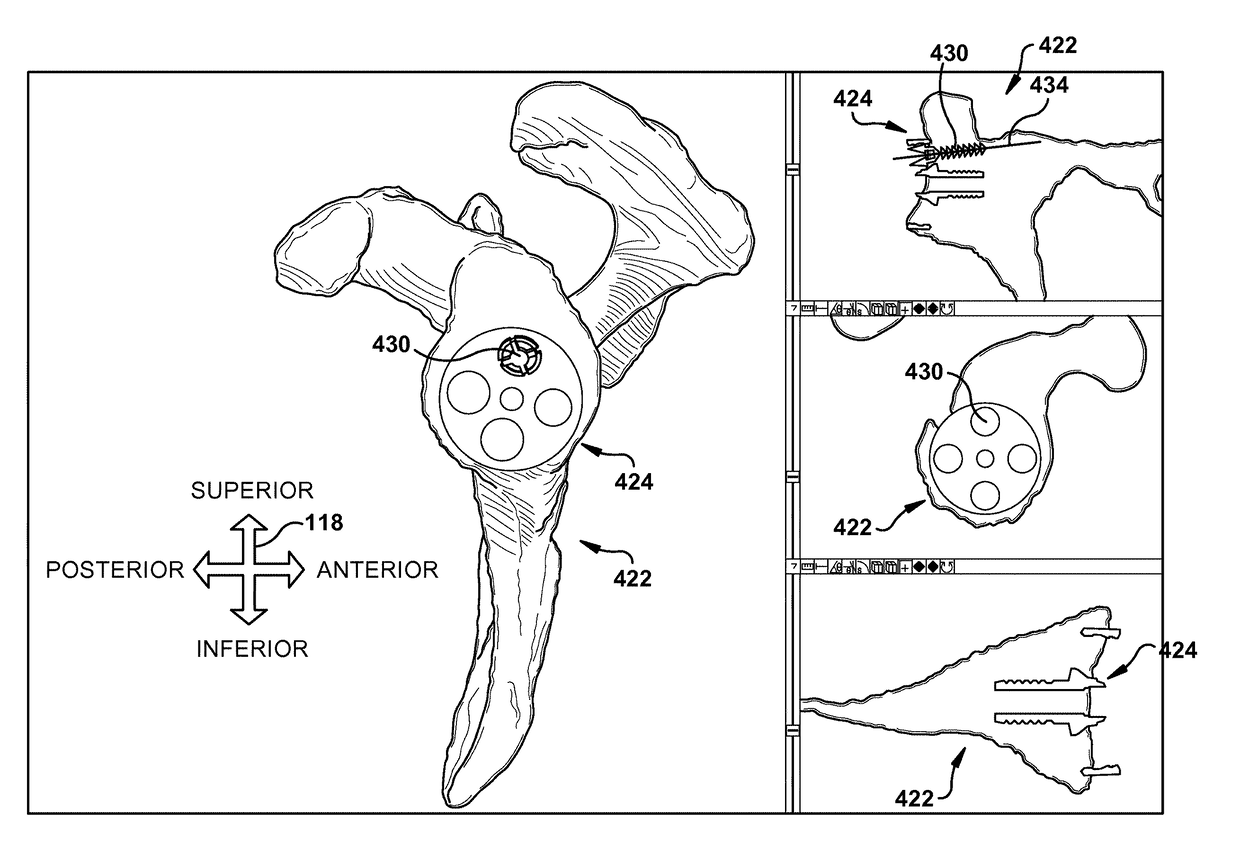
[0033]The patient tissue is shown and described herein at least as a scapula 100 and the prosthetic implant component is shown and described herein at least as a glenoid component 216, but the patient tissue and corresponding prosthetic implant component could be any desired types such as, but not limited to, hip joints, shoulder joints, knee joints, ankle joints, phalangeal joints, metatarsal joints, spinal structures, long bones (e.g., fracture sites), or any other suitable patient tissue use environment for the present invention. For example, the prosthetic implant component could be an internal fixation device (e.g., a bone plate), a structure of a replacement / prosthetic joint, or any other suitable artificial device to replace or augment a missing or impaired part of the body.

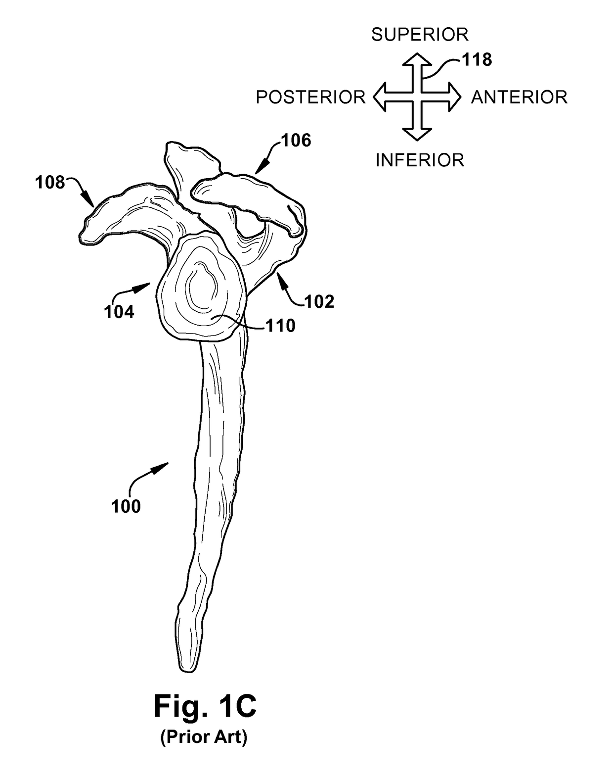
[0034]The term “lateral” is used herein to refer to a direction indicated by directional arrow 118 in FIG. 1C; the lateral direction in FIG. 1C lies substantially within the plane of the drawing and includ...


PUM


Abstract

A method of preoperative planning and provision of patient-specific surgical aids includes creating a virtual model of a native patient tissue. A virtual device is placed into a predetermined device orientation relative to the virtual model of the native patient tissue. At least one predetermined landmark orientation is specified for placement of at least one virtual landmark relative to the native patient tissue. A virtual patient-specific template containing the predetermined landmark orientation and having a landmark guiding feature is generated. At least one virtual patient-specific placement guide configured to interact simultaneously with at least one previously placed virtual landmark and the virtual device when the virtual device is in the predetermined device orientation is generated. A physical patient-specific template is created as a tangible representation of the virtual patient-specific template. A physical patient-specific placement guide is created as a tangible representation of the virtual patient-specific placement guide.

Description

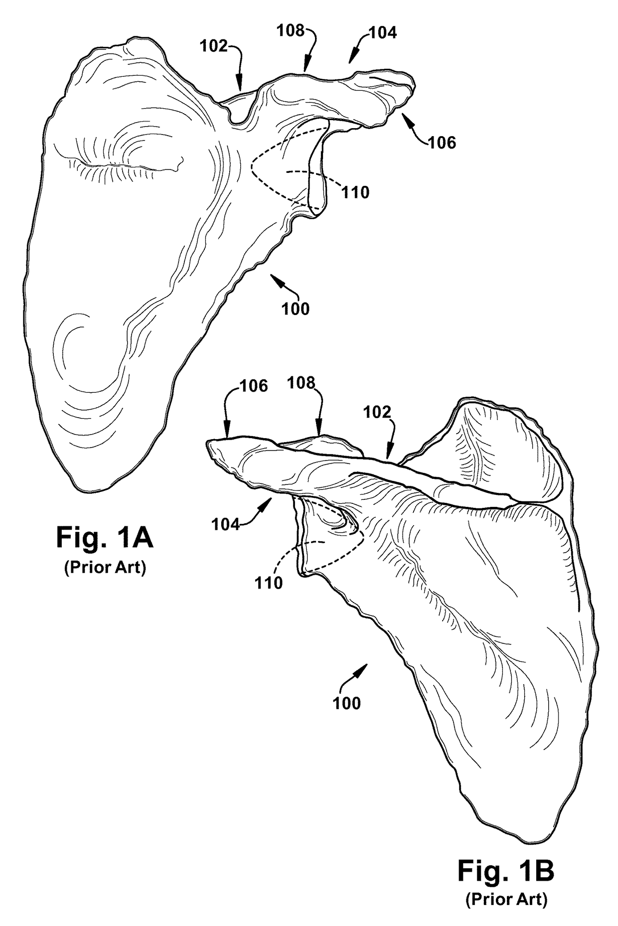
RELATED APPLICATION[0001]This application claims priority from U.S. Provisional Application No. 61 / 408,392, filed Oct. 29, 2010, the subject matter of which is incorporated herein by reference in its entirety.TECHNICAL FIELD[0002]The present invention relates to a preoperative planning system and, more particularly, to a system of preoperative planning and provision of patient-specific surgical aids.BACKGROUND OF THE INVENTION[0003]The scapula, commonly known as the “shoulder blade”, is a flat, triangular bone that lies over the back of the upper ribs. A right scapula 100 is depicted in posterior, anterior, and right side views in FIGS. 1A, 1B, and 1C, respectively. The posterior surface of the scapula 100 can be readily felt through a patient's skin. The scapula 100 serves as an attachment point for some of the muscles and tendons of the arm, neck, chest, and back, and aids in the movements of the arm and shoulder. The scapula 100 is also well padded with muscle, so that it may be ...

Claims


Application Information

Patent Timeline
Patent Type & Authority Patents(United States)
IPC IPC(8): G06F17/50A61B17/17A61B34/10A61B17/56A61F2/40A61B34/00A61F2/46
CPCA61B17/1739A61B34/10A61B17/1778A61B34/25A61B2017/568A61B2034/105A61B2034/108A61F2/4081A61F2002/4633
Inventor IANNOTTI, JOSEPH P.BARSOUM, WAEL K.BRYAN, JASON A.O'NEILL, PETER D.
Owner THE CLEVELAND CLINIC FOUND
Learn More