Muon tracker and muon tracking method

a technology of muon tracker and tracking method, which is applied in the direction of x/gamma/cosmic radiation measurement, radiation particle tracking, instruments, etc., can solve the problems of complicated calculation of muon transit time, difficult to detect the muon track in real time, etc., and achieves the effect of simple configuration and swift detection

Active Publication Date: 2017-08-01
KK TOSHIBA
View PDF7 Cites 0 Cited by
  • Summary
  • Abstract
  • Description
  • Claims
  • Application Information

AI Technical Summary

Benefits of technology

[0013]To solve the above problems, it is an object of present invention to provide techniques in which a muon track can be swiftly detected with a simple configuration.

Problems solved by technology

However, this technique requires complicated calculation for obtaining the muon transit time.
Accordingly, for instance, it is difficult to detect the muon track in real time.

Method used


Image

  • Muon tracker and muon tracking method
  • Muon tracker and muon tracking method
  • Muon tracker and muon tracking method

Examples


Embodiment Construction

[0023]Embodiments of the present invention are now described with reference to the accompanying drawings.

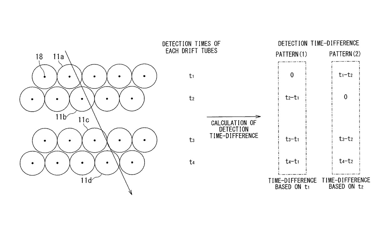
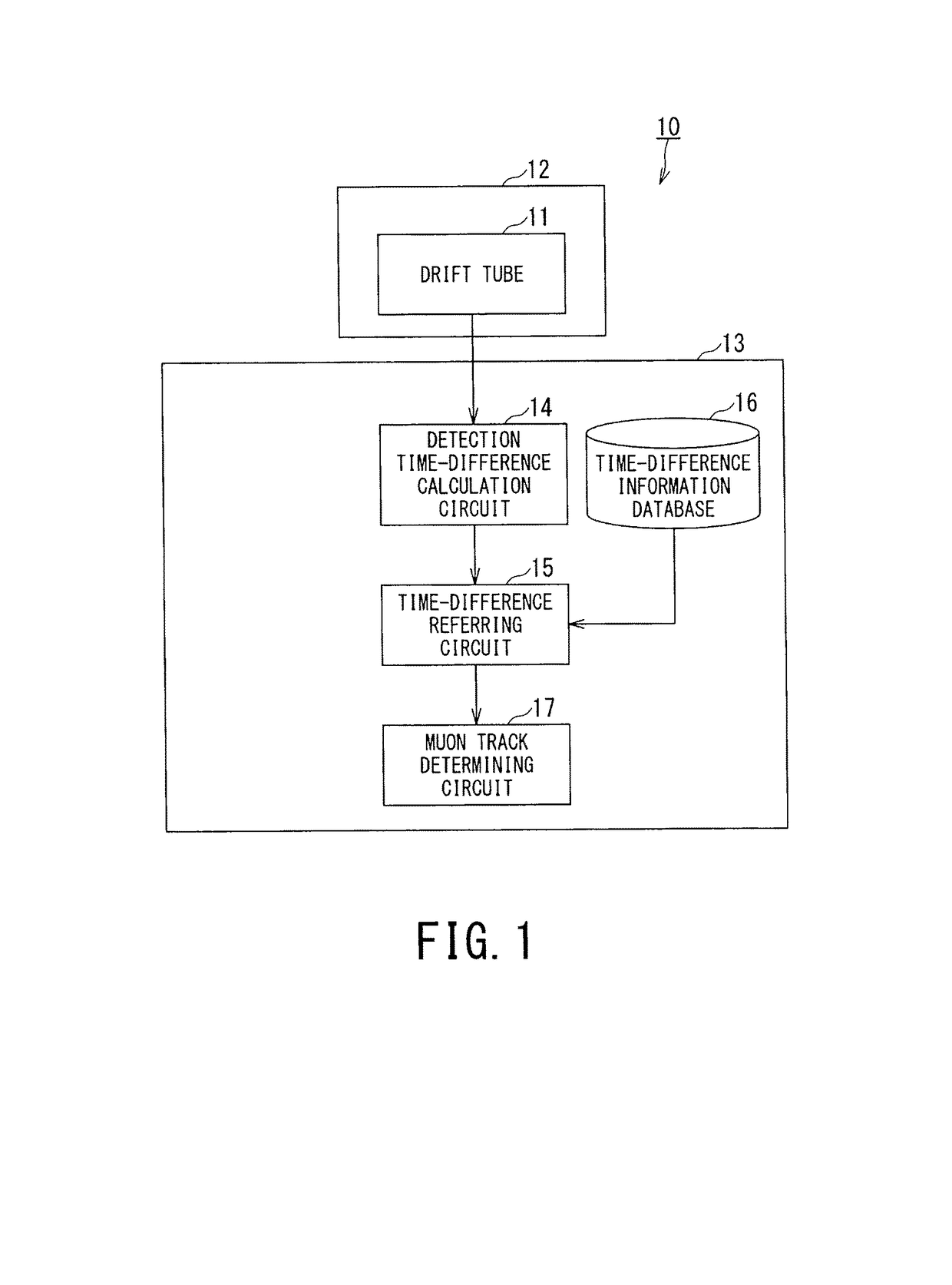
[0024]A muon tracker 10 according to an embodiment shown in FIG. 1 comprises: a drift tube detector 12 comprising a plurality of drift tube arrays, each of the drift tube arrays comprises a plurality of drift tubes 11 aligning parallel to each other, wherein each of the drift tubes 11 is configured to detect a muon passing therein; a detection time-difference calculation circuit 14 configured to calculate a detected time-difference between a plurality of time data detected at least two of the drift tubes 11 that detect the muon passing therein; a time-difference information database 16 that stores a relationship between a plurality of predetermined tracks of the muon passing the drift tube detector 12 and a predetermined time-difference of possible detected time data to be detected at least two of the drift tubes 11 where each of the plurality of predetermined tracks passes; a ti...


PUM


Abstract

A muon tracker includes a drift tube detector having a plurality of drift tube arrays, a detection time-difference calculation circuit configured to calculate a detected time-difference between a plurality of time data detected at least two of the drift tubes, a time-difference information database that stores a relationship between a plurality of predetermined tracks of the muon passing the drift tube detector and a predetermined time-difference of possible detected time data to be detected at least two of the drift tubes where each of the plurality of predetermined tracks passes, a time-difference referring circuit configured to refer the detected time-difference calculated at the detection time-difference calculation circuit with the predetermined time-difference stored in the time-difference information database, and a muon track determining circuit configured to determine a muon track as the predetermined track of the muon corresponding to the predetermined time-difference that matches the best with the detected time-difference.

Description

CROSS-REFERENCE TO RELATED APPLICATION[0001]This application is based upon and claims the benefit of priority from Japanese Patent application No. 2014-004523, filed on Jan. 14, 2014, the entire content of which is incorporated herein by reference.BACKGROUND OF THE INVENTION[0002]Field of the Invention[0003]Embodiments of the present invention relate to a technique of detecting a muon track.[0004]Related Art[0005]Among techniques of imaging an interior of a structure, techniques of seeing through the interior by observing muons reaching the surface of the Earth have been known. These techniques have been suitably used for large structures into which access is difficult, including, for instance, volcanoes and pyramids.[0006]Among the techniques of seeing through the interior of a structure using muons, transmission methods of measuring attenuation of a muon particle flux, and scattering methods of measuring Coulomb multiple scattering angles of muons have been known. Among the scatte...

Claims


Application Information

Patent Timeline
Patent Type & Authority Patents(United States)
IPC IPC(8): G01T1/18G01T5/00G01T1/29H01J47/02H01J47/08
CPCG01T5/00G01T1/2935H01J47/02H01J47/08
Inventor NAKAYAMA, KOHICHIMIYADERA, HARUOYOSHIOKA, KENICHISUGITA, TSUKASAKUME, NAOTOBAN, YUICHIRO
Owner KK TOSHIBA
Why Eureka
Try Eureka