
Wireless transmission of nuclear instrumentation signals

a technology of nuclear instrumentation and transmission signals, which is applied in nuclear engineering, nuclear elements, greenhouse gas reduction, etc., can solve the problems of increasing the potential for damage, increasing the cost of refueling outages, and not even considering the cost of trained work crews. cost,

Active Publication Date: 2017-08-01
WESTINGHOUSE ELECTRIC CORP
View PDF12 Cites 0 Cited by
  • Summary
  • Abstract
  • Description
  • Claims
  • Application Information

AI Technical Summary

Benefits of technology

The invention provides a method and system for monitoring the condition of a nuclear reactor pressure vessel in a radioactive environment. The system includes an instrument that senses the condition of the reactor pressure vessel, a powered wireless transmitting modem that sends a signal indicative of the condition to a receiving modem, and a signal processing unit that determines the condition of the reactor pressure vessel from the wireless transmitted signal. The wireless transmitting modem may be connected to another modem to ensure continued function in case of failure. The instrument may be connected to multiple transmitting modems and the receiving modem may be in line of sight of the transmitting modems. The condition monitored may include control rod position, coolant water bulk temperature, coolant water level, radiation level, and ion chamber level. The system allows for real-time monitoring of the reactor pressure vessel during power generation operations and disassembly.

Problems solved by technology

Given an estimated cost of $20,000 to $25,000 per hour of lost critical path time, this one day period would represent a cost of approximately $500,000 per refueling outage without even taking into consideration the cost of the trained work crew.
Additionally, the repeated manipulation of the signal cables increases the potential for damage, leading to the need to repair and / or replace the cables and / or the related hardware.

Method used


Image

  • Wireless transmission of nuclear instrumentation signals
  • Wireless transmission of nuclear instrumentation signals
  • Wireless transmission of nuclear instrumentation signals

Examples


Embodiment Construction

[0027]The present invention will now be described more fully hereinafter with reference to the accompanying drawings, in which examples of the invention are shown. The invention may, however, be embodied in many different forms and should not be construed as limited to the examples set forth herein. Rather, these examples are provided so that this disclosure will be thorough and complete, and will fully convey the scope of the invention to those skilled in the art. Like numbers refer to like elements throughout.

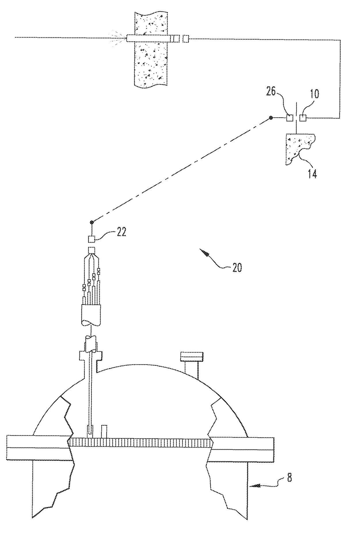
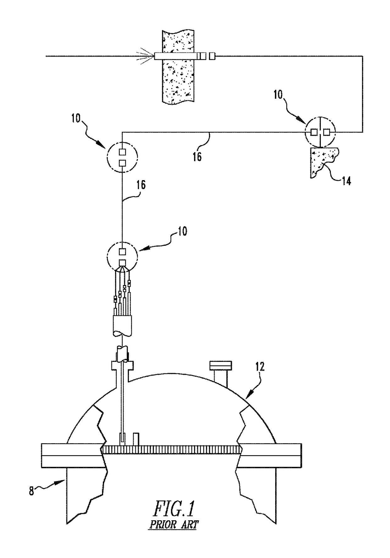
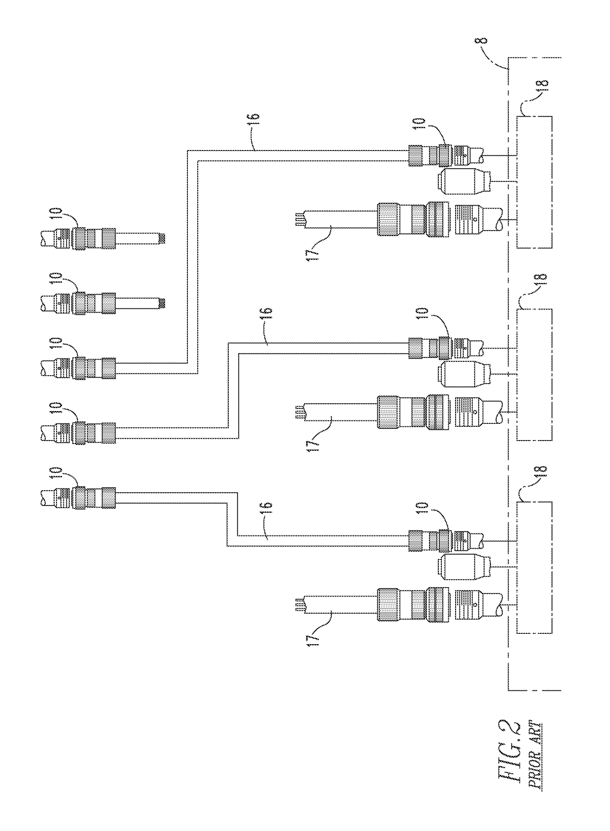
[0028]FIGS. 3 and 4 illustrate an example improved monitoring system 20 in accordance with the present invention that provides for the monitoring of one or more conditions of a nuclear reactor pressure vessel 8 without the need of cable sections 16 (such as those shown in FIGS. 1 and 2). As shown in FIG. 4, the multi pin connectors 10 (shown in FIGS. 1 and 2) at both ends of the former cable section 16 are replaced with wireless modems 22,26, with each modem 22,26 having a re...


PUM


Abstract

A system for monitoring a condition of a nuclear reactor pressure vessel disposed in a radioactive environment includes an instrument structured to monitor a condition of the nuclear reactor pressure vessel; a powered wireless transmitting modem disposed in the radioactive environment, the wireless transmitting modem being electrically coupled to the instrument; a receiving modem disposed in the line of sight of the transmitting modem, the receiving modem being in wireless communication with the transmitting modem; and a signal processing unit electrically coupled to the receiving modem, the signal processing unit being structured to determine the condition of the nuclear reactor pressure vessel from the instrument. The transmitting modem is powered by a thermocouple disposed in or on the reactor pressure vessel.

Description

CROSS REFERENCE TO RELATED APPLICATION[0001]This application is a Continuation-In-Part application of U.S. application Ser. No. 12 / 577,789, entitled WIRELESS TRANSMISSION OF NUCLEAR INSTRUMENTATION SIGNALS, filed on Oct. 13, 2009.FIELD OF THE INVENTION[0002]The present invention is directed to monitoring of a nuclear reactor pressure vessel. More particularly, the present invention is directed to a system and method for wirelessly monitoring a condition of a nuclear reactor pressure vessel.BACKGROUND OF THE INVENTION[0003]The mechanical movement (i.e. insertion, withdrawal) and the associated monitoring of the position of the control rods are necessary functions for the operation of a nuclear reactor. Each of the instruments that perform this function typically is terminated with a power cable and one or two position indication cables that transmit signals from the instrument back to processing units, typically located in a control room. As used herein, the term instrument may also ...

Claims


Application Information

Patent Timeline
Patent Type & Authority Patents(United States)
IPC IPC(8): G21C17/00G21C17/10G21D7/04
CPCG21C17/00G21C17/10G21D7/04H04Q9/00Y02E30/30
Inventor MORRIS, RICHARD W.
Owner WESTINGHOUSE ELECTRIC CORP
Learn More