Implant for lower limb amputation

a technology for amputation stumps and implants, applied in the field of implants for distal load bearings, can solve the problems of inability to perform gritti-stokes amputation techniques, risk of infection, and small distal bony area to allow end bearings, so as to improve the load bearing capacity of the amputation stumps

Active Publication Date: 2017-08-08
HOPITAUX UNIVS DE GENEVE
View PDF10 Cites 0 Cited by
  • Summary
  • Abstract
  • Description
  • Claims
  • Application Information

AI Technical Summary

Benefits of technology

[0007]An object of this invention is to provide an implant for lower limb amputation, namely transfemoral or transtibial amputation, to improve the load bearing capacity of the amputation stump.
[0008]It is advantageous to provide an implant for transfemoral or transtibial amputation that may be implanted with simple surgical intervention steps.
[0009]It is advantageous to provide an implant for transfemoral or transtibial amputation that is versatile and flexible.

Problems solved by technology

If femoral amputation is more proximal, the Gritti-Stokes amputation technique cannot be performed.
When Gritti-Stokes amputation cannot be implemented, a standard transfemoral amputation is performed; however the distal bony area is too small to receive and allow for end bearing.
The latter technique allows the stump's distal load to rest on the prosthesis's skeleton, however, an important drawback is the risk of infection because of the implant passing through the skin.
Another risk is the rupture of the intramedullar implant.

Method used


Image

  • Implant for lower limb amputation
  • Implant for lower limb amputation
  • Implant for lower limb amputation

Examples


Embodiment Construction

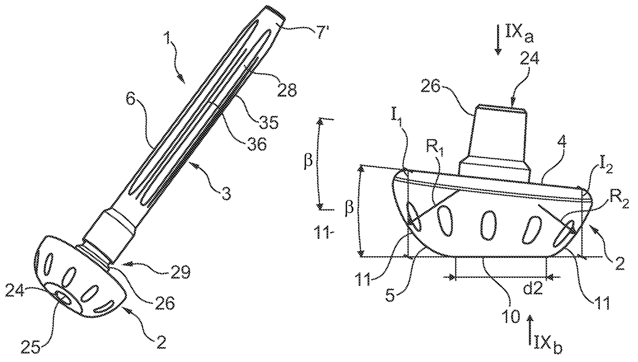
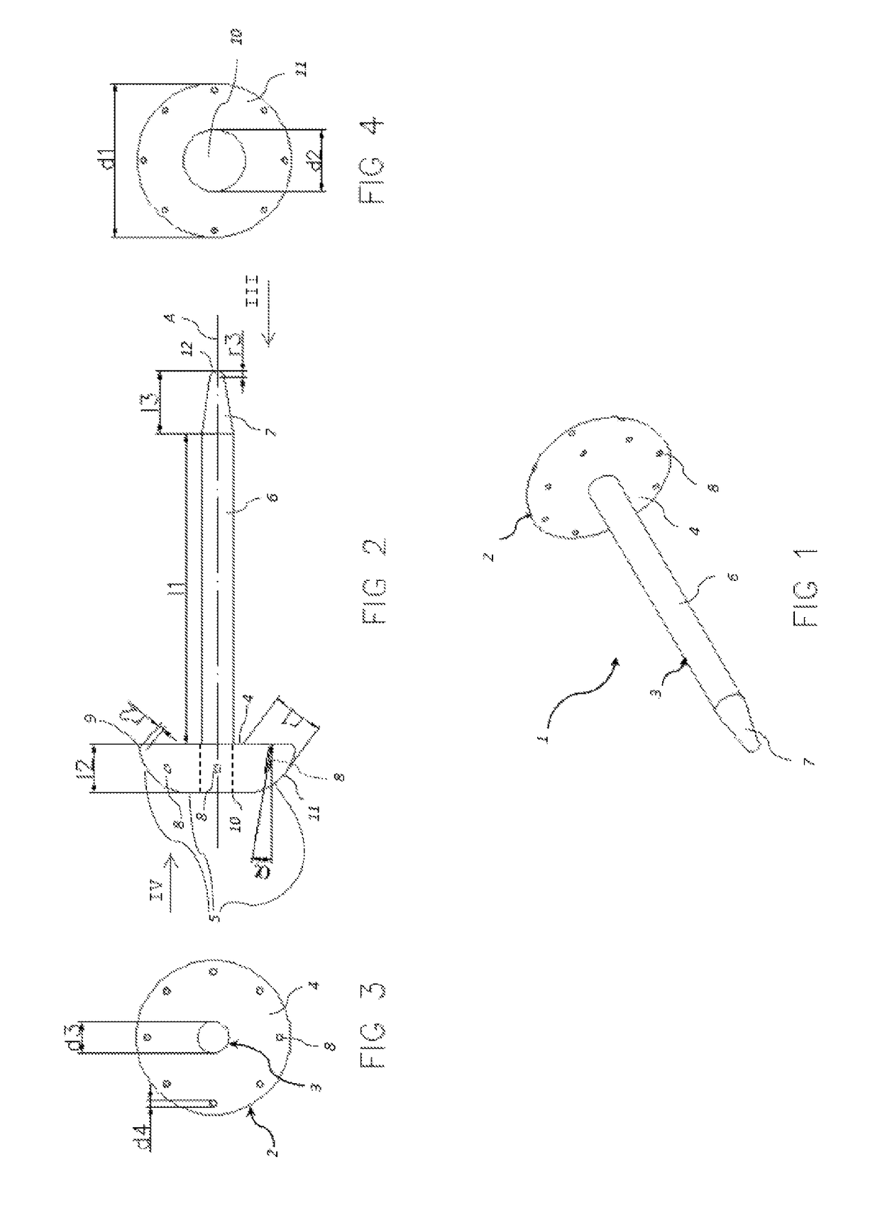
[0048]Referring to the figures, an implant 1 for transfemoral or transtibial amputation is shown, comprising a base 2 and a stem 3 configured to be inserted in a medullary canal 23 of an amputated femur bone, and in a variant, in the medullary canal of an amputated tibia bone. The use of the implant according to this invention is most advantageous for transfemoral amputations, however the advantages it confers are also useful for transtibial amputations. For simplicity, the invention embodiments will be described in relation to the amputation of the femur bone, being understood that the invention may also be used in the case of a transtibial amputation with the same features except for dimensional and angular adjustments taking into account the different anatomy of the above knee and below knee parts and bones of a person's leg.

[0049]The stem 3 is rigidly connected to, and extends from, the base 2. The stem is manufactured as a separate part configured to be assembled to the base an...


PUM


Abstract

Implant for transfemoral or transtibial amputation comprising a stem (3) and a base (2), the base (2) comprising a bone support surface (4) on one side and on an opposite side a soft tissue load bearing surface (5). The stem extends from the base perpendicular to the bone support surface and is configured for insertion in a medullary canal (23) of an amputated bone (20), the bone support surface (4) being configured for abutment against a severed end (22) of said amputated bone. A diameter (d1) of the base is configured to be larger than an average diameter of a shaft (21) of said severed bone, the soft tissue load bearing surface (5) comprising a generally planar or slightly curved central portion (10) and a convexly curved radially outward portion (11) with a curvature greater than the central portion, the central portion (10) being oriented at an angle of between 4° to 8° to the bone support surface.

Description

PRIORITY STATEMENT[0001]This application is a national stage application under 35 U.S.C. §371 of PCT International Application No. PCT / IB2014 / 058608, which has an International filing date of 28 Jan. 2014 and which claims priority under 35 U.S.C. §119 to European Application No. 13153017.2 filed 29 Jan. 2013. The contents of each application recited above are incorporated herein by reference in their entirety.FIELD OF THE INVENTION[0002]This invention relates to an implant for distal load bearing in amputation of the lower limb, in particular for above knee amputation.BACKGROUND OF THE INVENTION[0003]Amputation of the lower limb is one of the most widely performed surgeries. The levels of amputation which decrease the length of the lower limb may generally be divided into two groups: those for which the bone surface after amputation is large enough to accept the distal delivery and those which require a deferred charge area. For above knee amputation, the weight bearing area is on t...

Claims


Application Information

Patent Timeline
Patent Type & Authority Patents(United States)
IPC IPC(8): A61F2/28A61F2/78
CPCA61F2/78A61F2/2814A61F2002/2825A61F2002/2892A61F2002/7887
Inventor LACRAZ, ALAIN
Owner HOPITAUX UNIVS DE GENEVE
Why Eureka
Try Eureka