Turbine
a turbine and engine technology, applied in the field of turbines, can solve the problems of reducing and achieve the effect of improving the efficiency of the turbine and further reducing the loss of mixing
- Summary
- Abstract
- Description
- Claims
- Application Information
AI Technical Summary
Benefits of technology
Problems solved by technology
Method used
Image


Examples
first embodiment
[0057](First Embodiment)
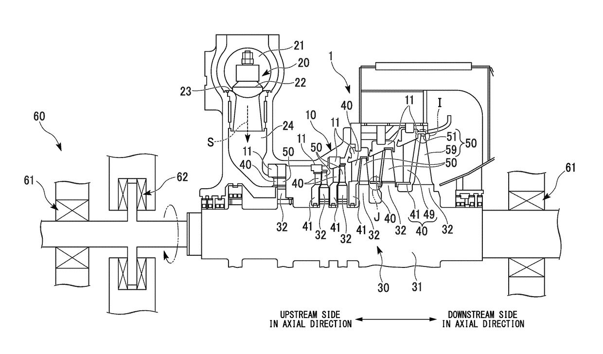
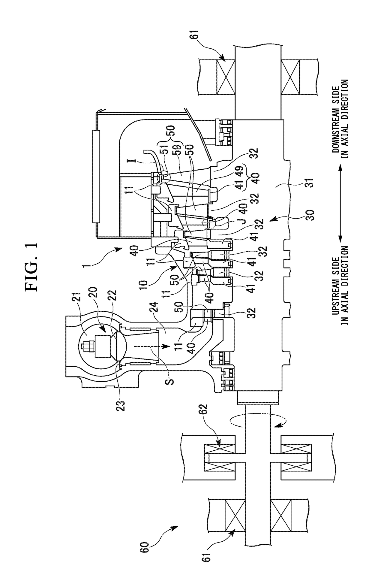
[0058]FIG. 1 is a cross-sectional view showing the schematic configuration of a steam turbine (a turbine) 1 according to a first embodiment of the present invention.
[0059]The steam turbine 1 mainly includes a casing (a stator) 10, an adjusting valve 20 that adjusts the amount and the pressure of steam S flowing into the casing 10, a shaft body (a rotor) 30 that is rotatably provided inward in the casing 10 and transmits power to a machine (not shown) such as an electric generator, a turbine vane 40 held in the casing 10, a turbine blade (a blade body) 50 provided at the shaft body 30, and a bearing unit 60 that supports the shaft body 30 so as to be able to rotate the shaft body 30 around an axis.
[0060]The casing 10 has a hermetically sealed internal space and becomes a flow path of the steam S. The casing 10 has a ring-shaped divider outer ring (an accommodating concave body) 11 solidly fixed to the inner wall surface of the casing and surrounds the shaft bo...
second embodiment
[0101](Second Embodiment)
[0102]Next, a steam turbine 2 according to a second embodiment of the present invention will be described using the drawings.
[0103]FIG. 8 is an enlarged cross-sectional view of a main section of the steam turbine 2 and FIG. 9 is an enlarged cross-sectional perspective view of a main section of the steam turbine 2. In addition, in FIGS. 8 and 9, the same constituent elements as those in FIGS. 1 to 7 are denoted by the same signs and a description thereof is omitted here.
[0104]As shown in FIG. 8, the steam turbine 2 is different from the steam turbine 1 in terms of a trailing edge end portion 70 equivalent to the trailing edge end portion 56 of the steam turbine 1.
[0105]The trailing edge end portion 70 is made of an axial fin extending from the tip shroud 51 to the downstream side in the axial direction, and thus the axial gap gb is narrowed. A tapered surface 70a that is connected to the guide curved surface 57 and also gradually directed to the radially inwa...
third embodiment
[0117](Third Embodiment)
[0118]Next, a steam turbine 3 according to a third embodiment of the present invention will be described using the drawings.
[0119]FIG. 12 is an enlarged cross-sectional perspective view of a main section of the steam turbine 3 and FIG. 13 is a blade row diagram of the steam turbine 3. In addition, in FIGS. 12 and 13, the same constituent elements as those in FIGS. 1 to 11 are denoted by the same signs and description thereof is omitted.
[0120]As shown in FIG. 12, the steam turbine 3 is different from the steam turbine 1 described above in that a guide pathway 81 is formed on the guide curved surface 57 of the steam turbine 1.
[0121]The guide pathway 81 is formed in a groove shape, as shown in FIG. 12, and extends in a curved manner from a starting end of the guide curved surface 57 (a terminus of the outer peripheral surface 53C) to the trailing edge end portion 56 when viewed from the radially outward side to the radially inward side. More specifically, as sho...
PUM
 Abstract
Description
Claims
Application Information
 - R&D
- Intellectual Property
- Life Sciences
- Materials
- Tech Scout
- Unparalleled Data Quality
- Higher Quality Content
- 60% Fewer Hallucinations
Browse by: Latest US Patents, China's latest patents, Technical Efficacy Thesaurus, Application Domain, Technology Topic, Popular Technical Reports.
© 2025 PatSnap. All rights reserved.Legal|Privacy policy|Modern Slavery Act Transparency Statement|Sitemap|About US| Contact US: help@patsnap.com