X-ray CT apparatus

a technology of x-ray generator and ct apparatus, which is applied in the field of x-ray ct generator, can solve the problems of increasing reducing the weight of the x-ray ct apparatus, and increasing the frame weight, so as to enhance the degree of freedom of the x-ray irradiation field of the x-ray generator

Active Publication Date: 2017-08-15
MORITA MFG CO LTD
View PDF15 Cites 11 Cited by
  • Summary
  • Abstract
  • Description
  • Claims
  • Application Information

AI Technical Summary

Benefits of technology

[0008]In X-ray CT photography, in order to obtain an accurate CT image, it is preferable that the turning axis for the X-ray source and X-ray detector is kept as stable as possible. Rigidity enhancement of the frame supporting the X-ray source and the X-ray detector is effective to eliminate wobbling of the turning axis. However, it is necessary to thicken and strengthen the frame made of steel, which results in a problem in that the weight of the frame increases. When the weight of the frame increases, it is also necessary to use a reinforcement structure for a mechanism rotatably supporting the frame, which results in a further problem in that the weight of the X-ray CT apparatus increases.
[0029]Therefore, the plural bearings are provided while separated from each other along the turning axis, so that the wobble of the turning axis can be restrained.

Problems solved by technology

However, it is necessary to thicken and strengthen the frame made of steel, which results in a problem in that the weight of the frame increases.
When the weight of the frame increases, it is also necessary to use a reinforcement structure for a mechanism rotatably supporting the frame, which results in a further problem in that the weight of the X-ray CT apparatus increases.
Thus, the problem that the turning axis for the X-ray source and the X-ray detector is kept as stable as possible and the problem that the weight reduction of the X-ray CT apparatus is achieved are contradictory, and it is difficult to simultaneously solve these problems in the structure in which the X-ray source and the X-ray detector are supported by the steel frame.

Method used


Image

  • X-ray CT apparatus
  • X-ray CT apparatus
  • X-ray CT apparatus

Examples


Embodiment Construction

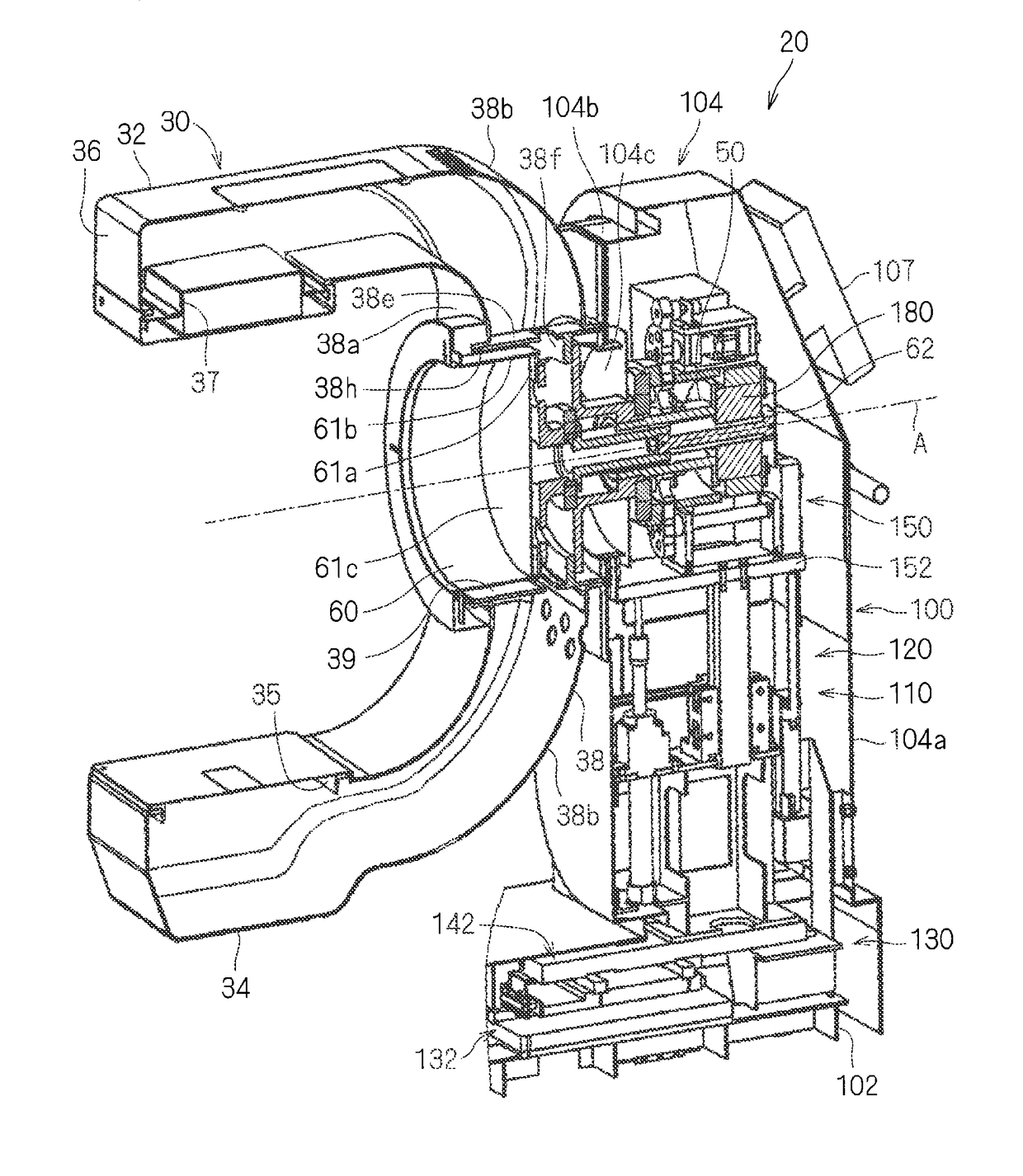
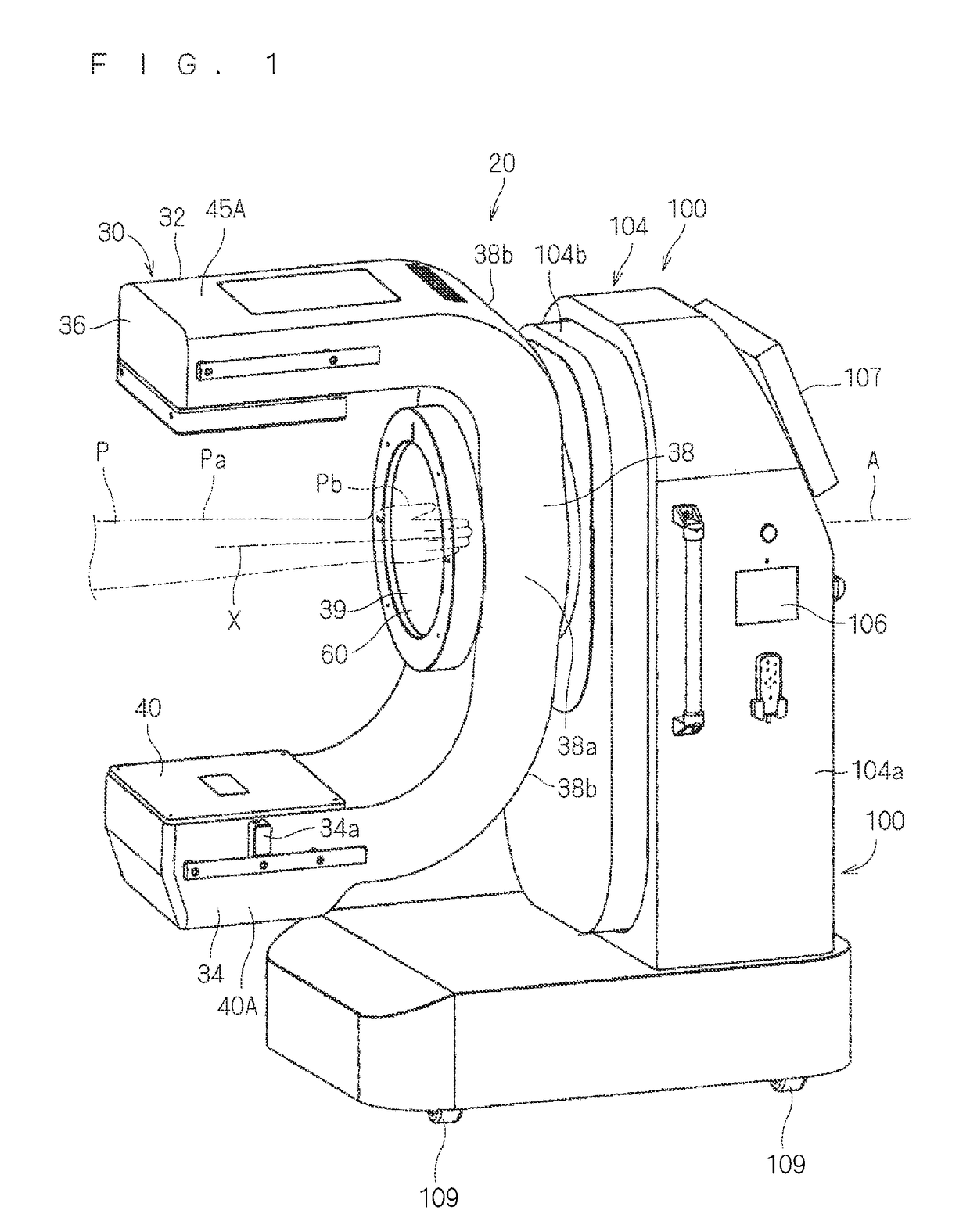
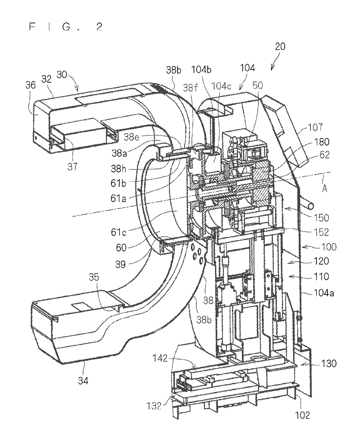
[0040]An X-ray CT apparatus according to a preferred embodiment will be described below. FIG. 1 is a perspective view illustrating an X-ray CT apparatus 20, FIG. 2 is a sectional view illustrating an internal structure of the X-ray CT apparatus 20, FIG. 3 is a sectional view illustrating a support part and a structure portion supporting the support part, and FIG. 4 is a sectional view illustrating the structure portion supporting the support part. FIG. 5 is a schematic sectional view of the X-ray CT apparatus, and FIG. 6 is a schematic partially sectional view taken on a line IV-IV in FIG. 5. Since FIGS. 5 and 6 are schematic views for the purpose of the description of a relationship among parts, sometimes the part illustrated in another view is simplified or eliminated. FIG. 7 is a perspective view illustrating a structure portion moving the support part in X-, Y-, and Z-directions.

[0041]1. Entire Structure

[0042]An entire structure of the X-ray CT apparatus 20 will be described wit...


PUM


Abstract

An X-ray CT apparatus including an X-ray generator, an X-ray detector, a support part, and a base that rotatably supports the support part. The support part includes an exterior part made of carbon fiber reinforced plastic, and the X-ray generator and the X-ray detector are supported by the exterior part while being opposed to each other. The base rotatably supports the support part such that the X-ray generator and the X-ray detector turn about a turning axis.

Description

BACKGROUND OF THE INVENTION[0001]Field of the Invention[0002]The present invention relates to an X-ray CT apparatus, particularly to a structure suitable for the X-ray CT apparatus in which a turning axis for an X-ray generator and an X-ray detector are horizontally arranged.[0003]Description of the Background Art[0004]For example, Japanese Patent Application Laid-Open No. 2011-025012 discloses an X-ray CT apparatus provided with a support arm that supports an X-ray source and an X-ray detector while the X-ray source and the X-ray detector are opposed to each other. The support arm includes a pair of arms that are supported in a cantilever manner while separated from each other, and an outline of the support arm is formed into substantially a U-shape as a whole. The support arm is arranged so as to be able to rotate about a horizontally-provided rotating axis. In the X-ray CT apparatus of Japanese Patent Application Laid-Open No. 2011-025012, the X-ray source and the X-ray detector ...

Claims


Application Information

Patent Timeline
Patent Type & Authority Patents(United States)
IPC IPC(8): A61B6/03H05G1/02A61B6/00
CPCA61B6/035A61B6/4405A61B6/4441H05G1/02
Inventor NIIZEKI, RYUICHIROYOSHIKAWA, HIDEKIKIRIMURA, SUSUMU
Owner MORITA MFG CO LTD
Why Eureka
Try Eureka