Power tool

a technology of power tools and power components, applied in the field of power tools, can solve the problems of having a complicated device configuration by any means, and achieve the effect of simple device configuration

Inactive Publication Date: 2017-08-15
MAKITA CORP
View PDF35 Cites 793 Cited by
  • Summary
  • Abstract
  • Description
  • Claims
  • Application Information

AI Technical Summary

Benefits of technology

[0037]According to the present invention, a power tool is provided which can realize various kinds of required operations in a simple device configuration. Other objects, features and advantages of the present invention will be readily understood after reading the following detailed description together with the accompanying drawings and the claims.

Problems solved by technology

In the known screw tightening machine, however, by provision of the construction in which rotation and impact are given to the tool bit, it is likely to have a complicated device configuration by any means.

Method used


Image

  • Power tool
  • Power tool
  • Power tool

Examples


first embodiment

(First Embodiment of the Invention)

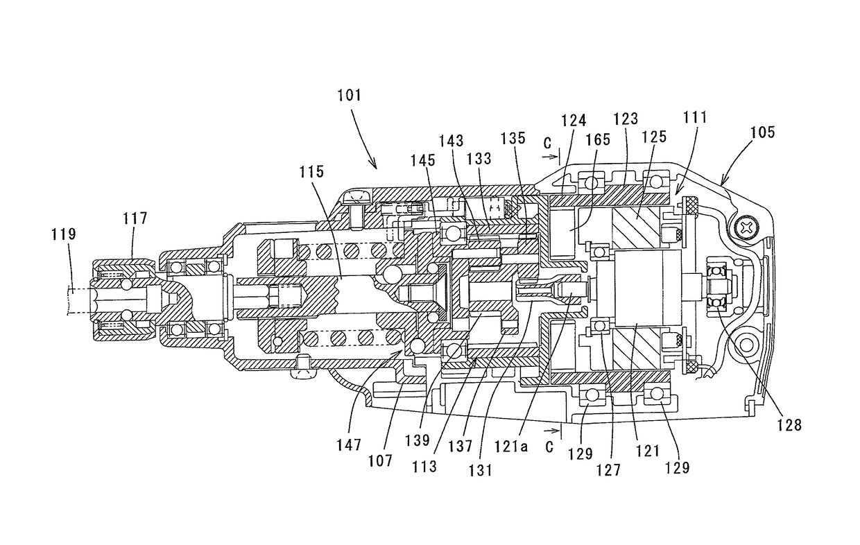
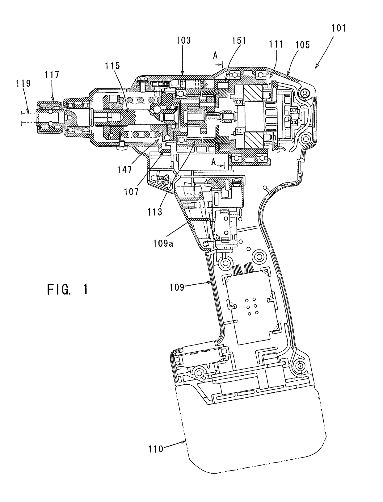
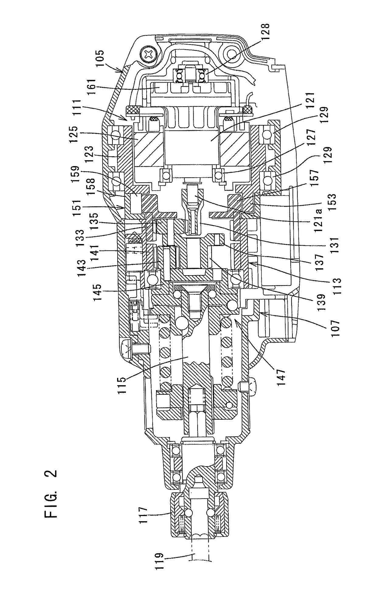
[0069]A first embodiment of the present invention is now described with reference to FIGS. 1 to 4. A battery-powered screwdriver is described as a representative embodiment of a hand-held power tool according to the present invention. FIG. 1 shows a screwdriver 101 according to this embodiment. As shown in FIG. 1, the screwdriver 101 according to this embodiment mainly includes a body 103 which forms an outer shell of the screwdriver 101, a screw bit 119 detachably coupled to a front end of a spindle 115 via a bit holder 117 in a front end region (left end region as viewed in FIG. 1) of the body 103, and a handgrip (handle) 109 connected integrally to the body 103. The body 103 and the screw bit 119 are features that correspond to the “tool body” and the “tool bit”, respectively, according to the present invention. Further, in this embodiment, for the sake of convenience of explanation, the side of the screw bit 119 is taken as the front and the op...

second embodiment

(Second Embodiment of the Invention)

[0094]A second embodiment of the present invention is now described with reference to FIGS. 5 to 8. In this embodiment, the first internal gear 133 is constantly driven by the outer rotor 123, and the first sun gear 131 can be driven and stopped by the inner rotor 121. To this end, the outer rotor 123 is directly connected to the first internal gear 133, and the bi-directional one-way clutch 151 is disposed between the inner rotor shaft 121a of the inner rotor 121 and the first sun gear 131. In the other points, this embodiment has the same construction as the above-described first embodiment. Therefore, components in this embodiment which are substantially identical to those in the first embodiment are given like numerals as in the first embodiment.

[0095]The bi-directional one-way clutch 151 has basically the same construction and function as that in the first embodiment. Due to arrangement of the bi-directional one-way clutch 151 between the inn...

third embodiment

(Third Embodiment of the Invention)

[0103]A third embodiment of the present invention is now described with reference to FIGS. 1 to 4. In this embodiment, the screw bit 119 is constantly driven by using one of the rotors, and in this state, the speed reduction ratio of the planetary gear mechanism 113 can be changed according to the load (tightening torque) on the screw bit 119 (the spindle 115) by using the other rotor, so that the rotation speed (screw tightening speed) of the screw bit 119 can be automatically changed.

[0104]The entire construction of the screwdriver 101 is the same as the above-described first embodiment and therefore it is not described. In this embodiment, it is constructed such that the inner rotor 121 and the outer rotor 123 are simultaneously driven when the trigger 109a is depressed.

[0105]For example, when the load is low until the screw is seated on the workpiece (the head of the screw comes into contact with the workpiece) after start of the screw tighteni...


PUM


Abstract

To provide a hand-held power tool which is equipped with a motor and can be used in a normal driving mode for a tip end tool and also in driving modes other than the normal driving mode. A power tool in which a tip end tool is driven by a motor to thereby perform a predetermined machining process on a workpiece, wherein the motor is a dual rotor motor comprising: an inner rotor; an outer rotor; and a stator including a driving coil mechanism, with the inner rotor and the outer rotor being coaxially disposed.

Description

FIELD OF THE INVENTION[0001]The present invention relates to a power tool that performs a predetermined operation on a workpiece with a tool bit driven by a motor.BACKGROUND OF THE INVENTION[0002]Japanese laid-open patent publication No. 2007-295773 discloses a hand-held power tool which is capable of controlling output torque of a tool bit driven by a motor. This power tool is constructed to tighten a screw by giving impact in the circumferential direction and rotation to the tool bit in the form of a screw bit.[0003]In the known screw tightening machine, however, by provision of the construction in which rotation and impact are given to the tool bit, it is likely to have a complicated device configuration by any means.DISCLOSURE OF THE INVENTIONProblems to be Solved by the Invention[0004]Accordingly, it is an object of the present invention to provide a power tool that can realize various kinds of required operations in a simple device configuration.Means for Solving the Problem[0...

Claims


Application Information

Patent Timeline
Patent Type & Authority Patents(United States)
IPC IPC(8): B25F5/00H02K7/14H02K16/00B25B23/00B25B21/00
CPCB25F5/001B25B23/00H02K7/145H02K16/00B25B21/00B25F5/008
Inventor HIRABAYASHI, SHINJIOTA, KENICHI
Owner MAKITA CORP
Why Eureka
Try Eureka