Wireless power communication

a technology of wireless power communication and wireless transmission, applied in the direction of digital transmission, inductance, baseband system details, etc., can solve the problems of imposing restrictions on the operating parameters of the system, affecting the efficiency of the system, so as to reduce the speed of zero bit decay

Active Publication Date: 2017-08-15
PHILIPS IP VENTURES BV
View PDF14 Cites 9 Cited by
  • Summary
  • Abstract
  • Description
  • Claims
  • Application Information

AI Technical Summary

Benefits of technology

[0010]In one embodiment, the adaptive power receiver may use Q-control to communicate to the wireless power supply. The shift in impedance caused by the Q-control will result in a change in the reflected impedance. The change in reflected impedance can be sensed by a change of amplitude of the current or voltage in the wireless power supply. Accordingly, by modulating the power signal with Q-control to change the reflected impedance, the receiver of the wireless power can effectively communicate with the wireless power supply, referred to generally as backscatter modulation.
[0012]Switching between discrete duty cycle values in order to create communication can introduce issues such as ringing that can distort communication. The distortion can be reduced or eliminated by ramping between the duty cycle values. For example, instead of adjusting the duty cycle directly from 20% to 30%, the duty cycle may be adjusted through a series of steps over a ramping time period to values in between 20% and 30%, which can reduce or eliminate distortion in the communication. The remote device's communication scheme may or may not include a period of time where the duty cycle is held constant after a ramping period.
[0014]The duration of the ramping can vary. For example, the time period for ramping during a bit time may depend on the number of transitions within the bit time. In addition, the time period for ramping to the first duty cycle may differ from the time period for ramping to the second duty cycle. For example, the time period for ramping can be selected to speed up or delay reaching a certain duty cycle value, thereby determining whether the duty cycle is achieved near the beginning, middle, or the end of the bit time. Delayed peak duty cycle transitions can reduce quick zero bit decays.

Problems solved by technology

There are a variety of factors that complicate development of efficient systems.
This inverse relationship between the distance and the mutual inductance may impose restrictions on the operating parameters of the system.
This system may gain some efficiency due to the utilization of additional coils in order to maintain an uncoupled resonant condition that is not dampened by the load, but may lose efficiency when coupling is tightened or the coils become physically closer.
But when additional coils are used in these configurations, cost may increase due to the added wire, and size may increase proportional to the added material.

Method used


Image

  • Wireless power communication
  • Wireless power communication
  • Wireless power communication

Examples


Embodiment Construction

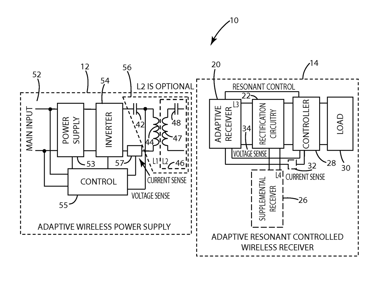
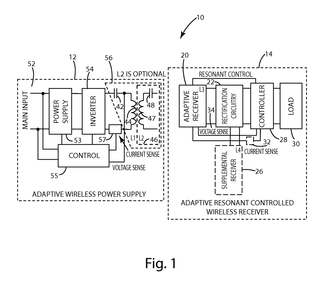
[0042]A wireless power supply system in accordance with an embodiment of the present invention is shown in FIG. 1 and designated 10. A remote device in accordance with one embodiment of the present invention can enable flexible power transfer, for example to allow the remote device to control the amount of power it receives, which can be used to communicate and / or provide an appropriate amount of power to the load. The wireless power supply system 10 includes a remote device 14 configured to receive wireless power and a wireless power supply 12 configured to transmit power. Although described in connection with a single remote device 14, the present invention is not limited to power transfer to just one remote device 14 and is well suited for supplying power to multiple remote devices, such as by supplying power sequentially or simultaneously. One or more of the remote devices 14 in this circumstance may be conventional remote devices.

[0043]The remote device can control the amount o...


PUM

PropertyMeasurementUnit
bit timeaaaaaaaaaa
timeaaaaaaaaaa
timeaaaaaaaaaa

Abstract

A remote device in accordance with the present invention includes an adaptive power receiver that receives wireless power from the wireless power supply by induction. The adaptive power receiver may be switched among two or more modes of operation, including, for example, a high-Q mode and a low-Q mode. By controlling the duty cycle of the switching between modes, the amount of energy received by the adaptive receiver may be controlled to communicate to the wireless power supply. This control is a form of adaptive resonance communication or Q control communication. Distortion can be reduced or eliminated by ramping between duty cycles with adjustment to intermediate duty cycle values.

Description

BACKGROUND OF THE INVENTION[0001]The present invention relates to wireless power transfer.[0002]Wireless power supply systems allow power to be transferred to an electronic device, such as a portable device, without the need for direct electrical connections. Wireless power transfer may be achieved using inductors, which produce magnetic fields when current flows through them. Conversely, current may be induced in an inductor when in the presence of a magnetic field, such as the magnetic field produced by another inductor. If two inductors are placed in proximity and one inductor is driven with a current, then the other inductor will produce a current even though the two inductors are not directly connected. This interrelationship between the two inductors is generally called inductive coupling, and many have used this phenomenon to transfer power without electrical connections.[0003]In fact, many of the fundamental principles of wireless power transfer have been known for 100 years...

Claims


Application Information

Patent Timeline
Patent Type & Authority Patents(United States)
IPC IPC(8): H01F27/42H02J5/00H01F38/14H04B5/00H04L25/49H02J50/12H02J50/80
CPCH02J5/005H01F38/14H02J50/12H02J50/80H04B5/0037H04L25/4902H04L25/0266H02J50/50H02J50/60H03H7/38
Inventor TAYLOR, JOSHUA B.MOORE, COLIN J.GRUICH, ROBERT D.
Owner PHILIPS IP VENTURES BV
Why Eureka
Try Eureka