
Method and magnetic resonance apparatus for echo planar imaging with data entry into k-space along a zigzag trajectory

a magnetic resonance imaging and data entry technology, applied in the field of echo planar magnetic resonance imaging, can solve the problems of image distortion, limit the possible resolution, and further technical requirements of mr apparatuses and epi imaging to be comparabl

Active Publication Date: 2017-08-22
MAX PLANCK GESELLSCHAFT ZUR FOERDERUNG DER WISSENSCHAFTEN EV +1
View PDF10 Cites 6 Cited by
  • Summary
  • Abstract
  • Description
  • Claims
  • Application Information

AI Technical Summary

Benefits of technology

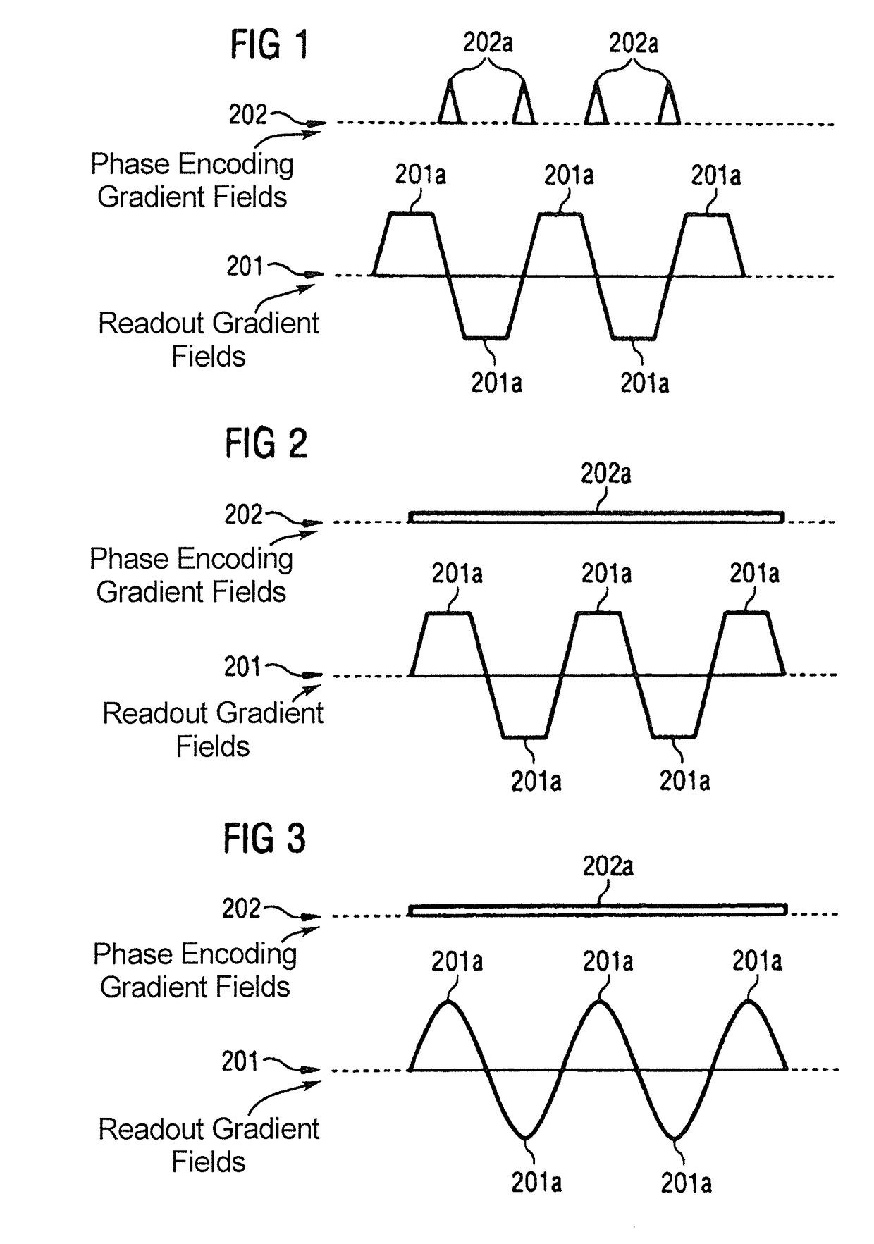
[0027]By employing a sequence of phase encoding gradient fields that are configured such that the phase encoding gradient fields continuously increment the phase of the transverse magnetization as a function of time, the acquisition of the raw data can be improved. In the technique subject to the present invention, raw data are continuously acquired that cover (fill) the entirety of k-space. Further, the effective strength of the gradient fields can be increased by simultaneously employing two independent gradient coils, e.g., for the phase encoding gradient and the oscillating readout gradient fields. In view of the physiological impact of the switched gradient fields on the patient (peripheral nerve stimulation), this can be an advantage.
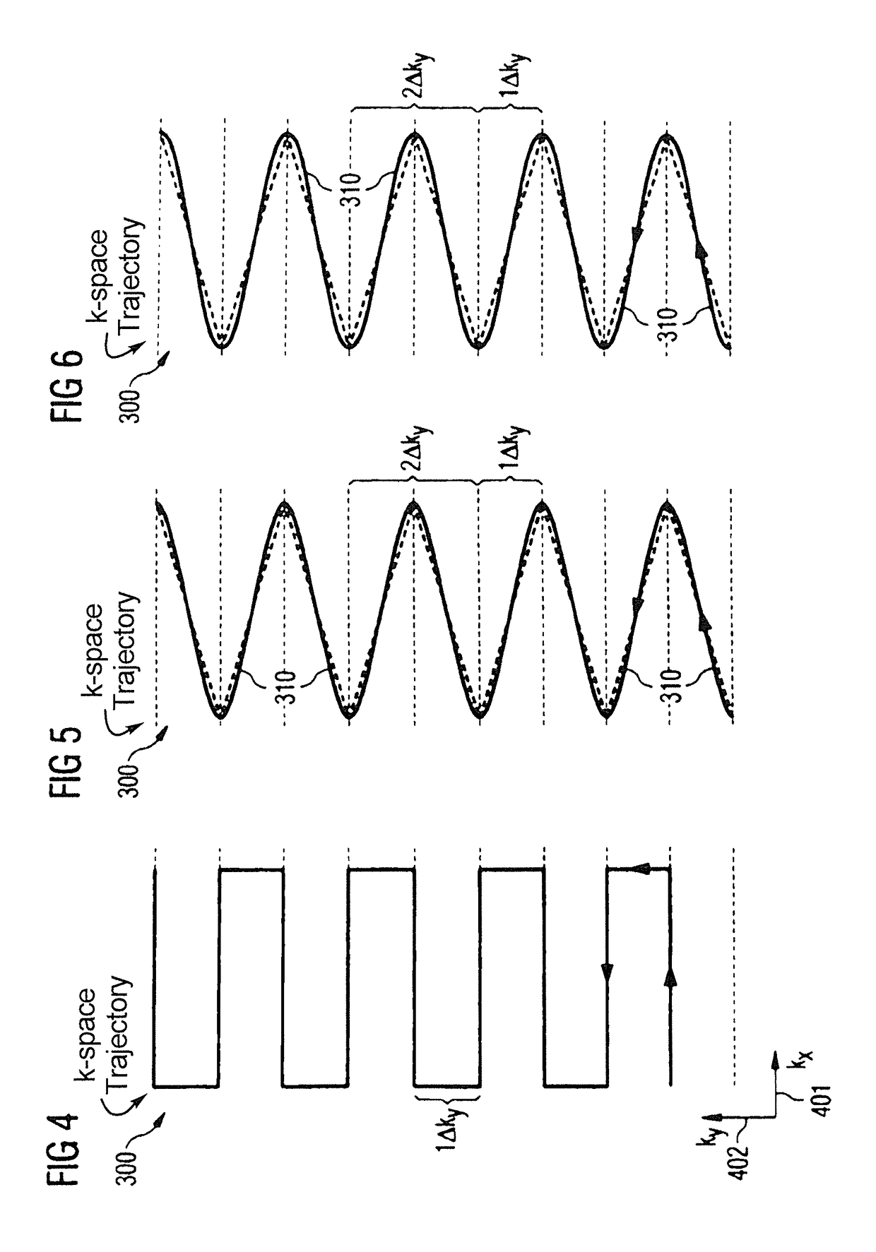
[0069]In such a scenario, phase differences caused by changing direction of the readout gradient fields can be avoided in the reference data that are employed for the determining of the reconstruction kernel. Errors and uncertainties in the determining of the reconstruction kernel thus can be reduced. It is possible that small errors in the temporal synchronization of the various components of the MR apparatus, in particular of the gradient system and the radio-frequency components, can cause a dependency of the reference data, as well as the raw data, on the inclination of the calibration trajectory, or the diagnostic trajectory, dependent on the sign. Therefore, it can be desirable to acquire parallel flanks of the calibration trajectory having the same sign as the readout gradient fields.

Problems solved by technology

Susceptibility artifacts can lead to image distortions that depend, inter alia, on the time between the various echoes of a gradient echo sequence (echo spacing).
Further, the T2* relaxation can limit the possible resolution.
Besides these physical limitations, it is also possible for further technical requirements of MR apparatuses and EPI imaging to be comparably demanding.
For example, typical EPI sequences impose high demands on the MR apparatus, because a comparably large number of gradient fields are rapidly switched.
Mechanical vibrations caused by this can lead to strong noise generation, which not only reduces patient comfort, but also requires a more sophisticated protection for the hearing of the patient (two-fold hearing protection by ear-phones and ear plugs).
Further, strong mechanical vibrations can lead to increased wear on the gradient coil and the supply line thereof, which causes increased maintenance costs or even damage to the MR apparatus.
However, employing of faster and stronger gradient systems is limited by the technological and physiological framework.
Therefore, a direct application of PPA techniques such as GRAPPA is not possible or only possible to a limited degree.
More sophisticated non-Cartesian PPA techniques, due to their increased complexity, such techniques have not been adopted for regular clinical use.
Further, a need exists for such techniques with limited technological and physiological stress due to gradient fields.

Method used


Image

  • Method and magnetic resonance apparatus for echo planar imaging with data entry into k-space along a zigzag trajectory
  • Method and magnetic resonance apparatus for echo planar imaging with data entry into k-space along a zigzag trajectory
  • Method and magnetic resonance apparatus for echo planar imaging with data entry into k-space along a zigzag trajectory

Examples


Embodiment Construction

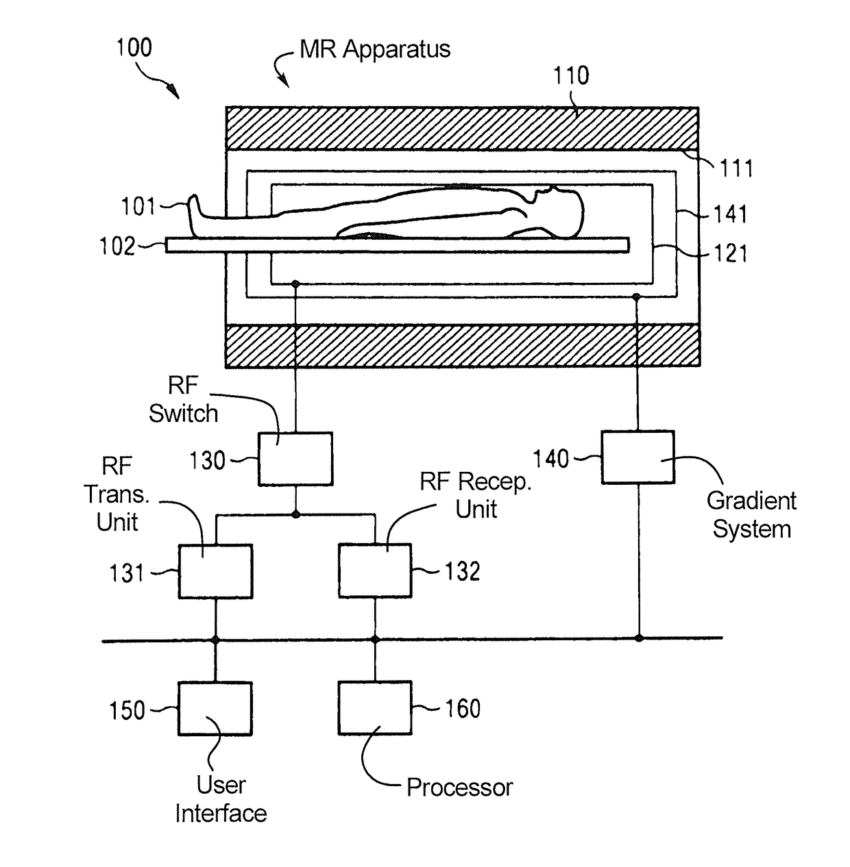
[0097]Hereinafter, the present invention is illustrated by means of preferred embodiments and with reference to the drawings. In the figures, like reference numerals denote like elements. In the figures, techniques for EPI MR imaging are described. In general, the techniques according to various embodiments of the present invention allow implementing zigzag-type trajectories having well-defined and specific parameters, e.g., curvature and inclination and / or distance of the flanks, for the acquiring of raw data. In particular, these techniques allow implementing zigzag-type trajectories for the acquiring of raw data which have flanks with comparably small curvature, i.e., particularly linear flanks. Such trajectories are referred to as ideal zigzag-type trajectories hereinafter, wherein it should be understood that particular technically caused deviations, respectively small residual curvatures can be present. Further techniques for the application of PPA methods, i.e., parallel imag...


PUM


Abstract

In a method and apparatus for echo planar magnetic resonance (MR) imaging sequence of phase encoding gradient fields and a sequence of readout gradient fields are applied in order to produce a well-defined zigzag-type trajectory for entering raw data into k-space. Zigzag-type trajectories can be achieved that have flanks without curvature, or without significant curvature. Cartesian methods for image reconstruction of parallel MR imaging are applied to echo planar MR imaging with such zigzag-type trajectories.

Description

BACKGROUND OF THE INVENTION[0001]Field of the Invention[0002]The present invention concerns a method for echo planar magnetic resonance imaging wherein raw data are acquired (entered into k-space) with a zigzag-type trajectory, as well as a magnetic resonance apparatus for implementing such a method. In particular, the invention concerns applying a certain series of phase encoding gradient fields, which enable the zigzag-type trajectory. The invention also concerns techniques for parallel imaging employing the zigzag-type trajectory.[0003]Description of the Prior Art[0004]Magnetic resonance (MR) tomography is an imaging modality that enables acquisition of two-dimensional or three-dimensional image data sets that allow structures in the interior of a patient to be shown in an image with a spatial resolution. MR data are acquired by operating an MR data acquisition unit magnetic to align magnetic moments of protons in a patient in a basic magnetic field or main magnetic field (B0), s...

Claims


Application Information

Patent Timeline
Patent Type & Authority Patents(United States)
IPC IPC(8): G01V3/00G01R33/48G01R33/561
CPCG01R33/4818G01R33/4824G01R33/5616G01R33/5611
Inventor PORTER, DAVID ANDREWHEIDEMANN, ROBIN
Owner MAX PLANCK GESELLSCHAFT ZUR FOERDERUNG DER WISSENSCHAFTEN EV
Learn More