
Integrated single-piece antenna feed

a single-piece, antenna feed technology, applied in the direction of antennas, antenna details, polarised antenna unit combinations, etc., can solve the problems of significant labor and manufacturing costs, degrade the antenna performance, and long fabrication and test times

Active Publication Date: 2017-08-22
OPTISYS INC
View PDF6 Cites 27 Cited by
  • Summary
  • Abstract
  • Description
  • Claims
  • Application Information

AI Technical Summary

Benefits of technology

The patent describes a special type of antenna feed that can produce electromagnetic waves. The feed includes a circular waveguide input, which is connected to a coaxial waveguide through a transition. The coaxial waveguide then connects to a polarizer, which divides the wave into two groups of waves. The polarizer then connects to a coaxial feed horn, which sends the waves out to the air. The special features of the antenna feed are that it has a unique design that allows for the efficient propagation of the electromagnetic waves. The technical effect of this design is that it increases the efficiency of the antenna feed and makes it more effective in transmitting signals.

Problems solved by technology

However, such support structure, e.g., one or more struts, dielectric, etc., unavoidably shadows, attenuates, or blocks, a portion of the aperture between the feed horn and the subreflector and consequently degrades the performance of the antenna.
Another problem with a conventional antenna feed is that each of the components, e.g., input section, polarizer, feed horn and subreflector, is generally constructed as a separate component.
The assembly, testing and fine tuning of such separately manufactured antenna feeds results in significant labor and manufacturing cost, long fabrication and test times, and potential for high variability of antenna performance between units.
Antennas located in space on a satellite are limited in material choices, and most dielectrics are not fit for space applications.
Similarly, the use of struts degrades performance and increases the stowed size of the antenna, making it more difficult and expensive to launch.

Method used


Image

  • Integrated single-piece antenna feed
  • Integrated single-piece antenna feed
  • Integrated single-piece antenna feed

Examples


Embodiment Construction

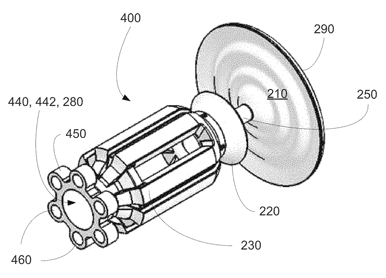
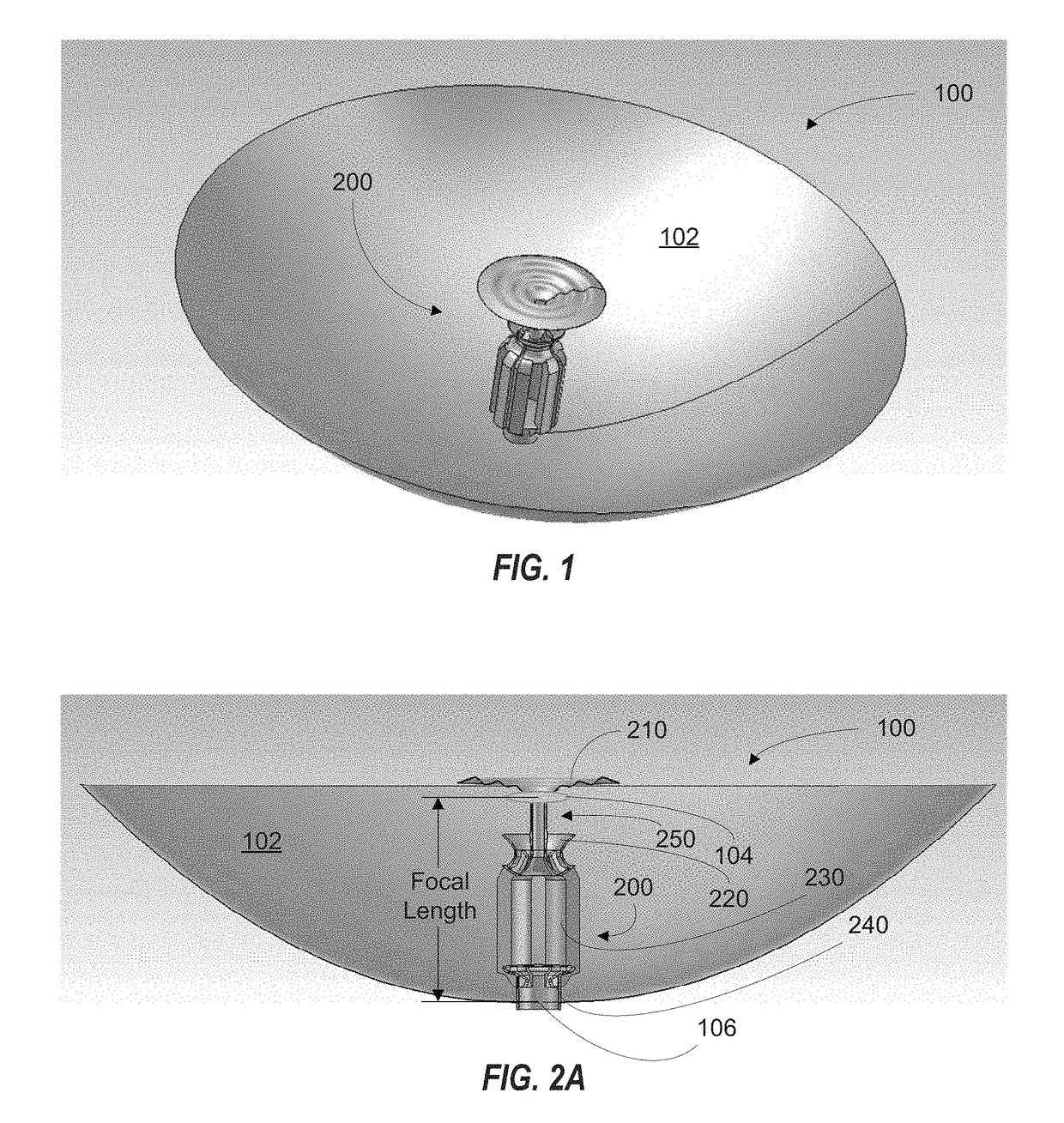
[0052]Embodiments of the present invention include an integrated single-piece antenna feed for use in communications systems such as SATCOM, or long range LOS communications links. The feed may include circular waveguide input, polarizer, coaxial feed horn with subreflector support, and subreflector as a single-piece metal component. This antenna feed may be used in conjunction with a parabolic ring-focus main reflector in a dish antenna system. A particularly useful feature of embodiments of the antenna feed is that the antenna feed is formed of an integrated “single-piece” and is not assembled from its individual components. Integrated embodiments and individual components of the invention described herein may be manufactured using three-dimensional (3D) metal printing, (also known in the industry as direct metal printing (DMP), or additive manufacturing) techniques known to one of ordinary skill in the art.

[0053]According to one embodiment, all components of various embodiments o...


PUM


Abstract

The invention is an integrated single-piece antenna feed, turnstile polarizer and antenna system suitable for satellite communications. One embodiment of the integrated single-piece antenna includes a circular waveguide input, a circular polarizer, a coaxial feed horn, subreflector and subreflector support. One embodiment of the circular polarizer features four branches of wrapped-single-ridged waveguide.

Description

CROSS-REFERENCE TO RELATED APPLICATIONS[0001]This US non-provisional patent application claims benefit and priority to U.S. provisional patent application No. 62 / 409,277 filed on Oct. 17, 2016, titled “INTEGRATED SINGLE-PIECE ANTENNA FEED”, the contents of which are incorporated by reference as if fully set forth herein.BACKGROUND OF THE INVENTION[0002]Field of the Invention[0003]The present invention relates generally to antennas and feeds for dish antennas. In particular, this invention relates to ring focus dish antennas for use in communications systems. Still more particularly, this invention relates to an integrated antenna feed for use with a ring focus dish antenna.[0004]Description of Related Art[0005]High gain antennas, used in applications such as satellite communications (SATCOM), or long range line-of-sight (LOS) communications links, require large aperture areas to achieve sufficiently high gains. Two primary methods by which these large aperture areas can be achieved ...

Claims


Application Information

Patent Timeline
Patent Type & Authority Patents(United States)
IPC IPC(8): H01Q13/02H01Q3/26H01Q21/24H01Q21/26H01Q15/14
CPCH01Q13/02H01Q3/26H01Q21/245H01Q21/26H01Q15/14H01Q1/288H01Q15/244H01Q19/13H01Q19/134H01Q19/19H01Q19/191H01Q19/193H01Q13/0208
Inventor HOLLENBECK, MICHAELSMITH, ROBERTCATHEY, CLINTONOPRA, JANOS
Owner OPTISYS INC
Learn More