Electrical receptacle connector

a technology of electric receptacles and connectors, applied in the direction of coupling device connections, coupling protective earth/shielding arrangements, two-part coupling devices, etc., can solve the problems of product defect-free rate and connector manufacturers' problems, and achieve the effect of improving the defect-free rate of connectors, improving the structural strength of these components, and facilitating the manufacture of grounding members and grounding plates

Active Publication Date: 2017-08-29
ADVANCED CONNECTEK INC
View PDF8 Cites 12 Cited by
  • Summary
  • Abstract
  • Description
  • Claims
  • Application Information

AI Technical Summary

Benefits of technology

[0015]In one embodiment, the electrical receptacle connector further comprises a first conductive sheet and a second conductive sheet. The first conductive sheet is disposed on the upper surface of the second tongue portion and shields the second terminals, and the second conductive sheet is disposed on the lower surface of the first tongue portion. Therefore, great shielding performance can be provided, and electromagnetic interference (EMI) and radiofrequency (RFI) to the connector can be reduced.
[0022]According to the embodiment of the instant disclosure, the conventional one-piece grounding plate is separated to be the grounding member, which is out of the first insulated housing, and the grounding plate, which is in the first insulated housing. The grounding member and the grounding plate are assembled to the first insulated housing separately. Therefore, the grounding member and the grounding plate do not need the gaps for inserting fixtures. As a result, the manufacturing of the grounding member and the grounding plate becomes easier, the structural strength of these components can be improved, and the product defect-free rate of the connector can be improved.
[0023]In addition, since the grounding member and the grounding plate do not have the gaps, the shielding performance can also be improved. Furthermore, since the grounding plate and the grounding member can be produced separately and can be adapted to other connectors having similar structures, the manufacturing of the connector can be more efficient.

Problems solved by technology

Therefore, how to improve the shielding performance, how to reduce the crosstalking, the radiofrequency interference (RFI), and the electromagnetic interference (EMI), and how to improve the product defect-free rate for the connector become issues for the connector manufacturers.

Method used


Image

  • Electrical receptacle connector
  • Electrical receptacle connector
  • Electrical receptacle connector

Examples


Embodiment Construction

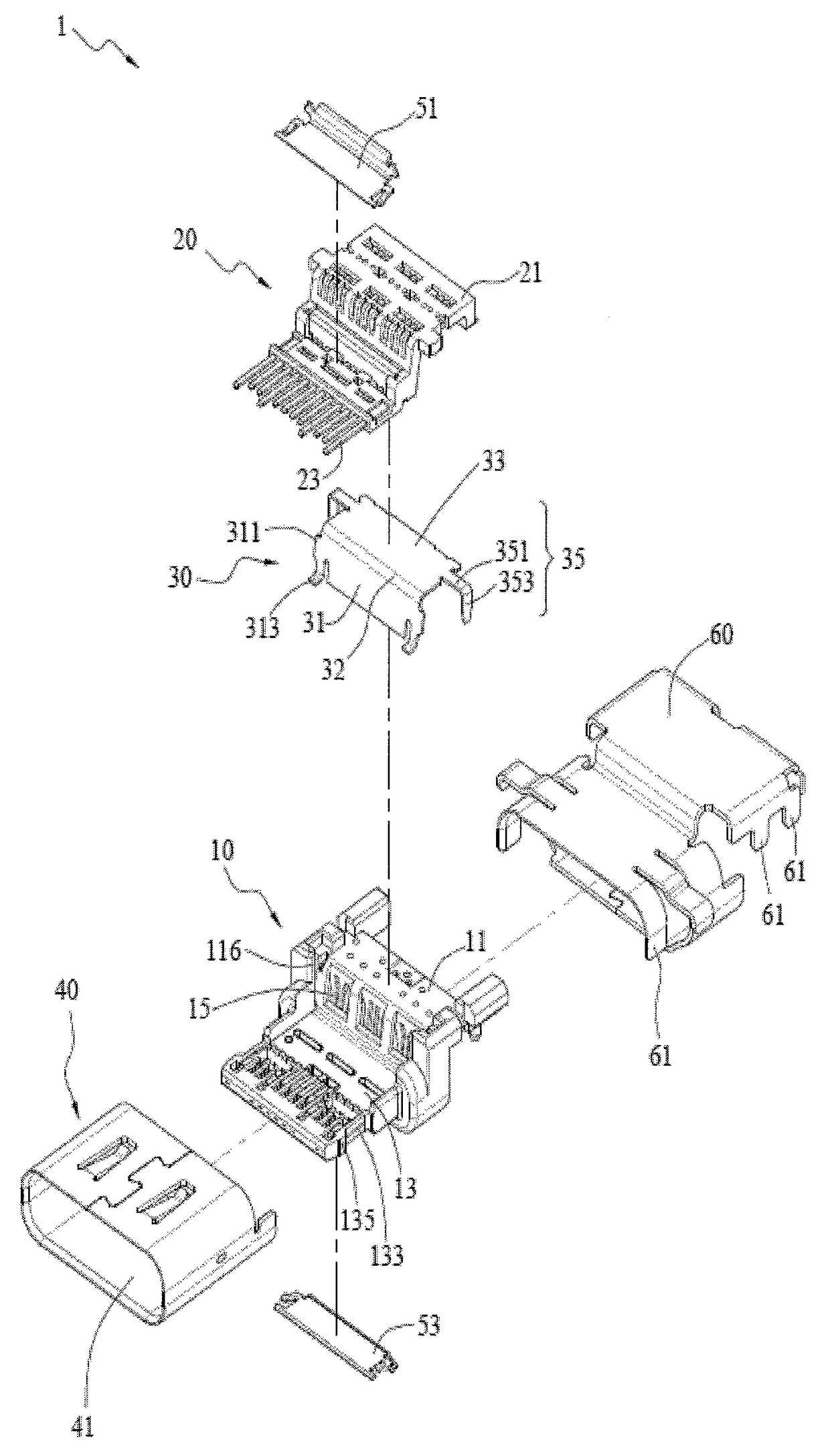
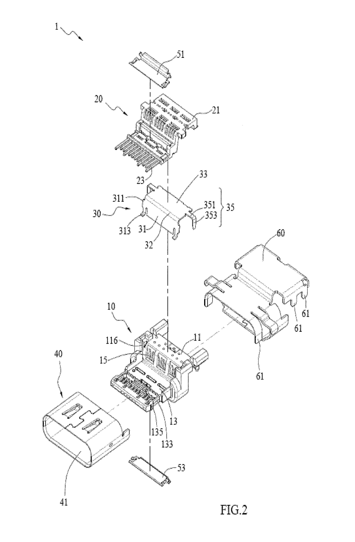
[0037]Please refer to FIGS. 1 and 2, which illustrate an electrical receptacle connector 1 of an exemplary embodiment of the instant disclosure. FIG. 1 and FIG. 2 respectively illustrate a perspective view and an exploded view of an electrical receptacle connector of one embodiment of the instant disclosure. As shown in FIGS. 1 and 2, one embodiment of the electrical receptacle connector 1 comprises a first terminal module 10, a second terminal module 20, a grounding member 30, and a metallic shell 40. The grounding member 30 is between the first terminal module 10 and the second terminal module 20. The metallic shell 40 encloses the assembly of the first terminal module 10 and the second terminal module 20. The metallic shell 40 has an insertion opening 41, and the first terminal module 10 and the second terminal module 20 are in the insertion opening 41.

[0038]Please refer to FIGS. 3 to 6, respectively illustrating a perspective view of the grounding member 30, an exploded view of ...


PUM


Abstract

An electrical receptacle connector includes a first terminal module, a grounding member, a second terminal module, and a metallic shell. The first terminal module includes a first insulated housing, a plurality of first terminals, and a grounding plate. The first insulated housing includes two grooves. The first terminals and the grounding plate are in the first insulated housing. A surface of the grounding plate is exposed from the first insulated housing. The grounding member includes two side protrusions and two protruding structures. The side protrusions are engaged with the grooves. The protruding structures are in contact with the grounding plate. The second terminal module is assembled to the first terminal module. The grounding member is between the first terminal module and the second terminal module.

Description

CROSS-REFERENCES TO RELATED APPLICATIONS[0001]This non-provisional application claims priority under 35 U.S.C. §119(a) on Patent Application No. 201510461610.6 filed in China, P.R.C. on Jul. 31, 2015, the entire contents of which are hereby incorporated by reference.FIELD OF THE INVENTION[0002]The instant disclosure relates to an electrical connector, and more particular to an electrical receptacle connector.BACKGROUND[0003]Generally, Universal Serial Bus (USB) is a serial bus standard to the PC architecture with a focus on computer interface, consumer and productivity applications. The existing Universal Serial Bus (USB) interconnects have the attributes of plug-and-play and ease of use by end users. Now, as technology innovation marches forward, new kinds of devices, media formats and large inexpensive storage are converging. They require significantly more bus bandwidth to maintain the interactive experience that users have come to expect. In addition, the demand of a higher perf...

Claims


Application Information

Patent Timeline
Patent Type & Authority Patents(United States)
IPC IPC(8): H01R13/648H01R13/6585H01R13/6461H01R24/62H01R107/00
CPCH01R13/6585H01R13/6461H01R24/62H01R2107/00
Inventor TSAI, YU-LUNHOU, PIN-YUANLIAO, CHUNG-FUKAO, YA-FENCHEN, LONG-FEISU, RUICHUANG, CHIEN-TSUNG
Owner ADVANCED CONNECTEK INC
Why Eureka
Try Eureka