Seismic monitoring

Active Publication Date: 2017-09-12
OPTASENSE HLDG LTD
View PDF9 Cites 15 Cited by
  • Summary
  • Abstract
  • Description
  • Claims
  • Application Information

AI Technical Summary

Benefits of technology

The present invention is a method for monitoring an area of interest using DAS and a geophone. The geophone detects seismic events and triggers recording of relevant data from the DAS sensor. This avoids the need for real-time processing of the data and allows for simpler and less expensive geophones to be used. The data can be processed further to reduce storage requirements and enable faster analysis without significant computational resources.

Problems solved by technology

Firstly geophone arrays are expensive.
The expense of geophone arrays means that the number of individual sensing elements in a geophone array which is deployed for long term monitoring is typically limited.
With a typical geophone array there may be a limit to the number of geophones that are used and thus the geophone array may only be able to monitor part of a deep-well site.
For current DAS sensors the instantaneous output from any individual sensing portion of fibre may not offer the same level of sensitivity as a conventional geophone.
However the fact that DAS allows a significant increase in the number of sensing channels available, coupled with the fact that DAS sensor typically have a data output rate which is greater than for conventional geophones, raises some potential problems with data storage and processing.
For long term microseismic monitoring the sensor array may be acquiring data constantly for relatively long periods of time.
Handling and storing this data is not a trivial task, especially as the area being monitored may often be in a remote and relatively hostile environment.
However with DAS sensors the higher data rate and relatively lower sensitivity of an individual sensing portion of fibre means that it is not straightforward to detect when an event of interest is occurring.
This would involve deploying significant computational resources in a field based interrogator unit with a significant impact on cost and complexity of the unit.

Method used


Image

  • Seismic monitoring
  • Seismic monitoring
  • Seismic monitoring

Examples


Embodiment Construction

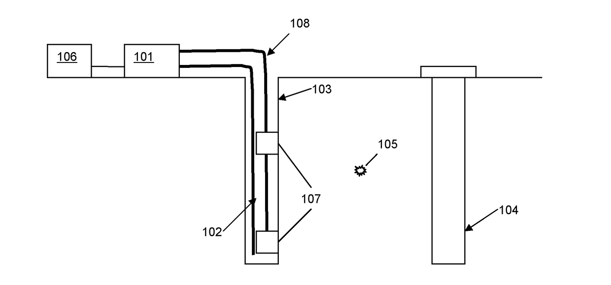
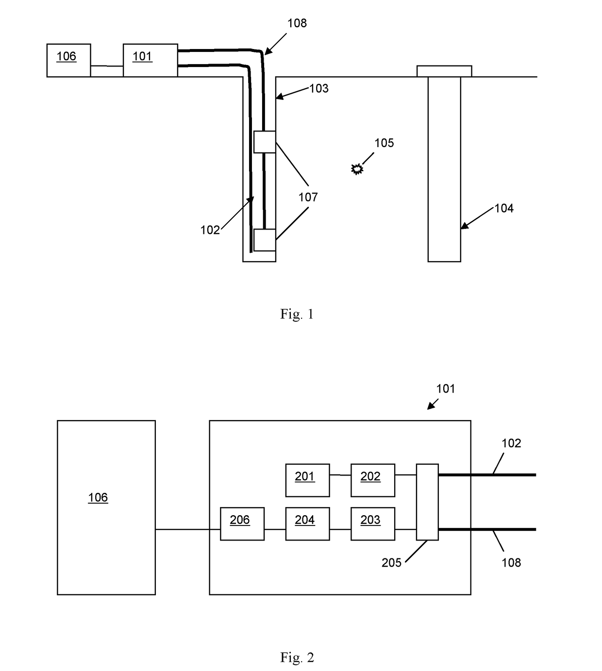
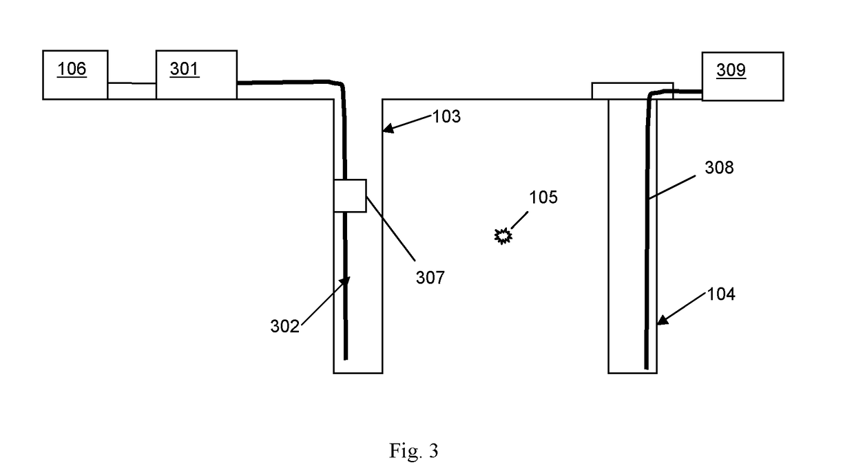
[0042]FIG. 1 illustrates a first embodiment of a seismic monitoring arrangement according to an embodiment of the present invention.

[0043]An interrogator unit 101 is removably connected to a first optical sensing fibre 102 to provide a distributed acoustic sensor. In this example the sensing fibre 102 is deployed to run the length of an observation wellbore 103 to provide long term monitoring of a reservoir in the vicinity of operational well 104, which may be a production well or an injection well. Other arrangements are possible however and the fibre could additionally or alternatively be at least partly buried near the surface of the area to be monitored. The sensing fibre 102 can be many kilometers in length and may, in this example, be at least as long as the depth of the observation wellbore which may be at least 1.5 km long. In this embodiment the sensing fibre may be a standard, unmodified single mode optic fibre such as is routinely used in telecommunications applications. ...


PUM


Abstract

The application describes methods and apparatus for seismic monitoring using fiber optic distributed acoustic sensing (DAS). The method involves interrogating a first optical fiber (102) deployed in an area of interest to provide a distributed acoustic sensor comprising a plurality of longitudinal sensing portions of fiber and also monitoring at least one geophone (107) deployed in the area of interest. The signal from the at least one geophone is analyzed to detect an event of interest (105). If an event of interest is detected the data from the distributed acoustic sensor acquired during said event of interest is recorded. The geophone may be co-located with part of the sensing fiber and in some embodiments may be integrated (307) with the sensing fiber.

Description

FIELD OF THE INVENTION[0001]This invention relates to seismic monitoring, and especially to long term seismic monitoring, using distributed fibre optic sensors, in particular distributed acoustic sensors.BACKGROUND OF THE INVENTION[0002]Seismic geophysical monitoring and surveying is used in a variety of applications. For example in the oil and gas sector seismic surveys may be conducted at numerous different stages of well construction and operation. In particular, once well construction has been completed and the wells are operational there may be a desire to perform long term seismic monitoring to monitor for any microseismic events so as to highlight any significant changes in the condition of the wells and / or the reservoir over time.[0003]Seismic monitoring may also be used for assessing reservoirs for the storage of hazardous or unwanted materials, for example in carbon dioxide sequestrations schemes. In these applications there may again be a desire to undertake long term sei...

Claims


Application Information

Patent Timeline
IPC IPC(8): G01H9/00G01V1/18G01V1/28G01V1/22G01V1/44
CPCG01V1/181G01V1/226G01V1/288G01H9/004G01V1/44G01V2210/123G01V2210/1429
Inventor LUMENS, PAUL GERARD EDMONDGRANDI, SAMANTHA
Owner OPTASENSE HLDG LTD
Why Eureka
Try Eureka