
Method of operating a wind farm

a wind farm and wind turbine technology, applied in the direction of wind turbines, engine control, motors, etc., can solve the problems of mainly induced unwanted effects, reduced electrical power production, and high load of this wind turbine, so as to avoid uncertainties derived from wind conditions measurement, less power, and faster and less expensive

Active Publication Date: 2017-09-12
GE RENEWABLE TECH WIND BV
View PDF8 Cites 3 Cited by
  • Summary
  • Abstract
  • Description
  • Claims
  • Application Information

AI Technical Summary

Benefits of technology

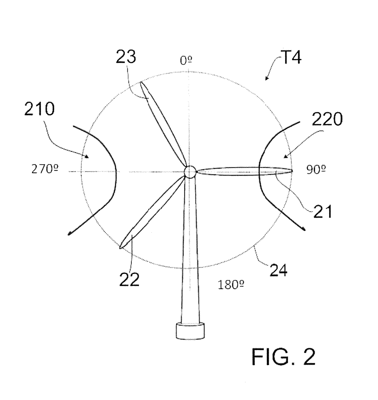
[0010]According to this aspect, once a wake situation is determined at a wind turbine located downstream, the blades of the wind turbine generating such a wake are individually adapted. Blade adaptation is dependent on each blade's angular position within the swept area. This way, conditions for blade and wind interaction are not homogenous over the complete swept area, thus creating an asymmetry in the rotor plane. The wake generated by said wind turbine can thus be deflected away from the swept area of the wind turbine located downstream. By adapting the blades individually, the asymmetry is created without displacing the whole rotor plane. Consequently, much lower inertias than those involved in prior-art methods need to be displaced, so that power requirements are significantly reduced and efficiency of the wind turbine may be increased. Furthermore, a substantially quicker response to varying wind conditions can be achieved. In addition, as the wake is deflected from the swept area of the wind turbine located downstream, stopping the wind turbines located upstream can be avoided, so that power production of the wind farm may thus be further increased.
[0012]Combinations of these embodiments may also be possible. Activating any of these systems (or combinations thereof) requires substantially less power than that required for moving the whole rotor with blades overhung structure. It is thus faster and less expensive.
[0013]In some embodiments, determining a possible wake situation may comprise detecting an overloading condition at the wind turbine. This may be achieved by load sensors provided on the blades of the wind turbines. By determining loads directly at the blades receiving the wake, wake situations can be detected substantially in real time. Furthermore, uncertainties derived from estimating loads from wind conditions measurements can also be avoided. In some embodiments the sensors may be arranged in the vicinity of the blade tip. Information about the outer regions of the swept area can thus be obtained. This way, premature overloading can be detected as soon as a wake generated by an upstream wind turbine starts intersecting with the swept area of a downstream wind turbine.
[0015]In some embodiments, individually adapting the blades of the second wind turbine comprises adapting the blades to a first extent. Then, the method may further comprise receiving, from the first wind turbine, feedback on the wake situation at the first wind turbine after individually adapting the blades of the second wind turbine to a first extent and, if the wake situation persists, adapting the blades of the second wind turbine to a further extent. This way, the extent to which the blades of the second wind turbine are adapted may be controlled precisely, so that the blades are not adapted in an unnecessary manner. Adapting the blades of the second wind turbine may reduce its electrical power production, while to a certain extent increasing loads. By limiting the extent to which blades are adjusted, electrical power production may be optimized.

Problems solved by technology

When the wake shed from a first wind turbine intersects with the swept area of a second wind turbine located downstream, it may cause high loads (particularly vibrations) in this wind turbine in case specific load mitigation strategies have been implemented.
This phenomenon may cause a reduction of electrical power production.
These unwanted effects are mainly induced by the high air speed that accompanies the vortexes generated, especially at the blade tips of the first wind turbine.
High loads may increase fatigue.
This strategy can negatively affect the total electrical power production of the wind farm as wind turbine power production is significantly reduced, if not completely eliminated, upon detection of certain wind conditions.
Furthermore, said commonly used management strategies do not typically comprise any optimization to account for other specific conditions e.g. when the wind turbine potentially receiving the wake situation is already not operating.
Nevertheless, this may not be possible in certain sites with specific constraints, as this strategy would require a larger area for installing the wind farm.
Moreover, the electrical infrastructure, and thus the costs, would also be increased.
However, systems for tilting a rotor are generally not provided on wind turbines and their implementation could be very costly.
Significant power is needed to displace such a big mass, said power thus reducing overall efficiency of the wind turbine by reducing electrical energy fed into the grid.
Besides, the use of the yaw system may be rather slow and, again, quite expensive.
Adapting the blades of the second wind turbine may reduce its electrical power production, while to a certain extent increasing loads.

Method used


Image

  • Method of operating a wind farm
  • Method of operating a wind farm
  • Method of operating a wind farm

Examples


Embodiment Construction

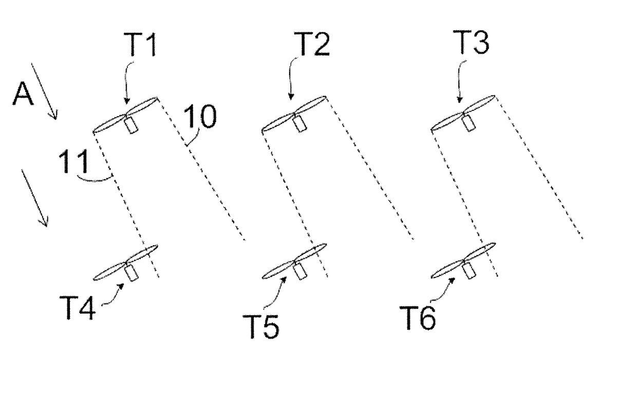
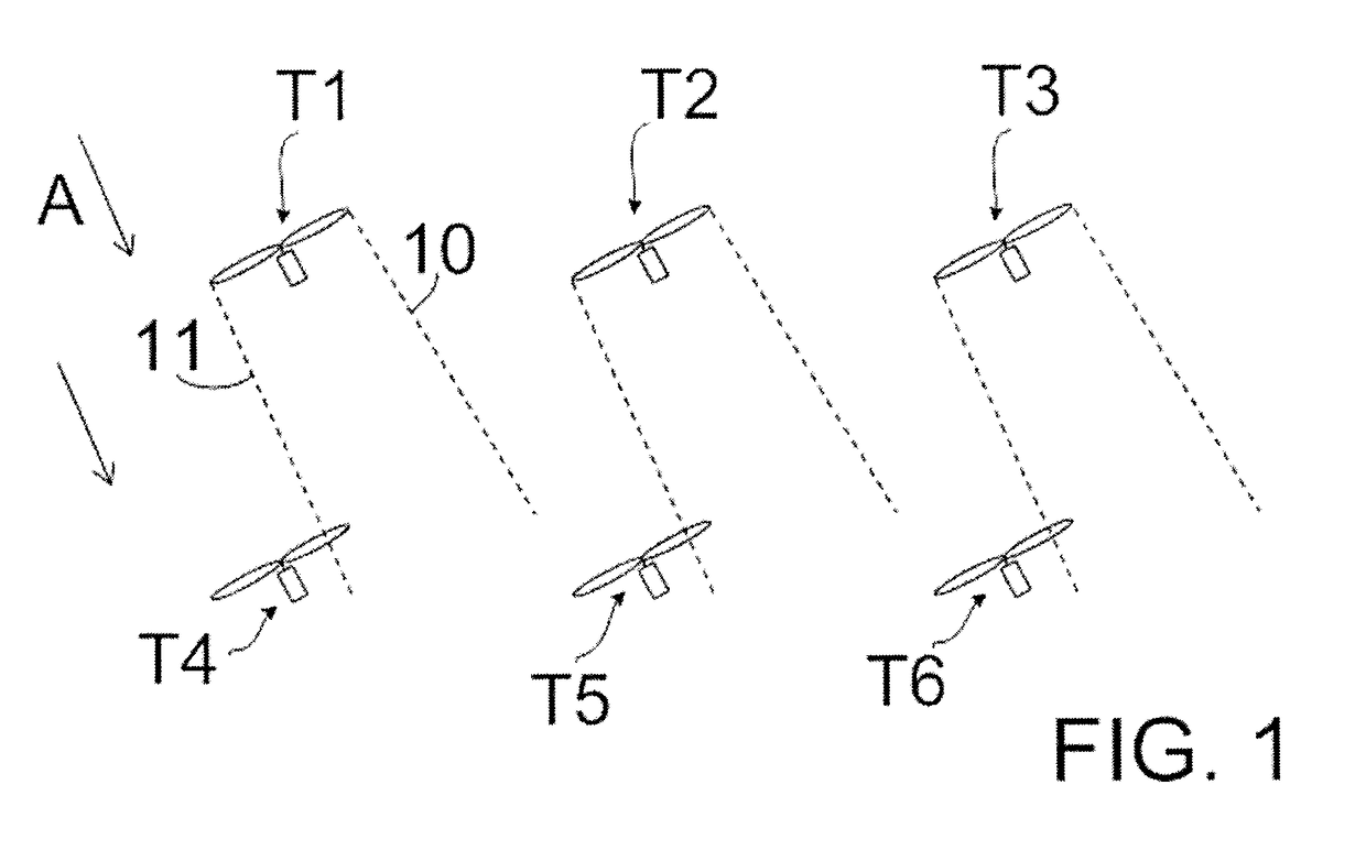
[0025]FIG. 1 shows a schematic representation of a wind farm comprising six wind turbines T1-T6 arranged in two rows, wherein three of them T1-T3 may be located upstream and the other three T4-T6 may be located downstream. Arrow A shows the wind direction and dashed lines 10, 11 schematically show the region affected by the wake generated by each wind turbine T1-T3 located upstream. In FIG. 1, due to the wind direction A, the wake of e.g. wind turbine T1, i.e. in the region of the dashed line 11, may intersect the swept area of wind turbine T4. It should be understood that the identification of T1-T3 as being located upstream and of T4-T6 as being located downstream depends on wind direction, so that these are only relative terms, which are applicable under certain conditions (arrow A). In particular, said identification would be reversed, i.e. T1-T3 located downstream and T4-T6 located upstream, if the wind direction were also reversed.

[0026]FIG. 2 shows a front view of a wind turb...


PUM


Abstract

Method of operating a wind farm comprising a plurality of wind turbines, each of the turbines having a plurality of blades, the method comprising determining a possible wake situation at a first wind turbine caused by a second wind turbine, the second wind turbine being located upstream of the first wind turbine, and individually adapting the blades of the second wind turbine such that a wake generated by the second wind turbine is deflected away from the first wind turbine.

Description

[0001]This application claims the benefit of European Patent Application 13382023.3 filed on Jan. 21, 2013 and U.S. Provisional Patent Application Ser. No. 61 / 804,105 filed on Mar. 21, 2013, the contents of which are hereby incorporated by reference in their entirety for all purposes.[0002]The present application relates to methods of operating a wind farm. The application further relates to systems suitable for carrying out such methods and to wind farms comprising such systems.BACKGROUND ART[0003]Modern wind turbines are commonly used to supply electricity into the electrical grid. Wind turbines generally comprise a rotor with a rotor hub and a plurality of blades. The rotor is set into rotation under the influence of the wind on the blades. The rotation of the rotor shaft drives the generator rotor either directly (“directly driven”) or through the use of a gearbox. The operation of the generator produces the electricity to be supplied into the electrical grid.[0004]Wind turbines...

Claims


Application Information

Patent Timeline
Patent Type & Authority Patents(United States)
IPC IPC(8): F03D7/04G05B15/02F03D7/02
CPCG05B15/02F03D7/022F03D7/048F05B2270/331Y02E10/723Y02E10/72F05B2270/204
Inventor BETRAN PALOMAS, JAUME
Owner GE RENEWABLE TECH WIND BV
Learn More