
Secondary battery and method for producing secondary battery

a secondary battery and manufacturing method technology, applied in the direction of batteries, sustainable manufacturing/processing, cell components, etc., can solve the problems of malfunction of current interrupt devices, achieve airtightness of secondary batteries, prevent generation and transmission of vibration, and improve the quality of secondary batteries

Active Publication Date: 2017-09-12
TOYOTA JIDOSHA KK
View PDF24 Cites 0 Cited by
  • Summary
  • Abstract
  • Description
  • Claims
  • Application Information

AI Technical Summary

Benefits of technology

[0024]According to a first aspect of the present invention, damage to a welded portion between a reverse plate and a collector tab caused by generation and transmission of vibration can be prevented.
[0025]As a result, a malfunction of the current interrupt device can be prevented, and airtightness of a secondary battery can be secured, which improves quality of the secondary battery.
[0026]According to a second aspect of the present invention, a sealing plate and a holder can be easily adhered to each other, and damage to the welded portion can be prevented with a simple structure.
[0027]According to a third aspect of the present invention, the sealing plate and the holder can be more easily and reliably adhered to each other.
[0028]According to a fourth aspect of the present invention, damage to the welded portion between the reverse plate and the collector tab caused by generation and transmission of the vibration can be prevented.
[0029]As a result, the malfunction of the current interrupt device can be prevented, and the airtightness of the secondary battery can be secured, which improves quality of the secondary battery.

Problems solved by technology

Therefore, the damage to the welded portion 43 may cause a malfunction of the current interrupt device 45.

Method used


Image

  • Secondary battery and method for producing secondary battery
  • Secondary battery and method for producing secondary battery
  • Secondary battery and method for producing secondary battery

Examples


first embodiment

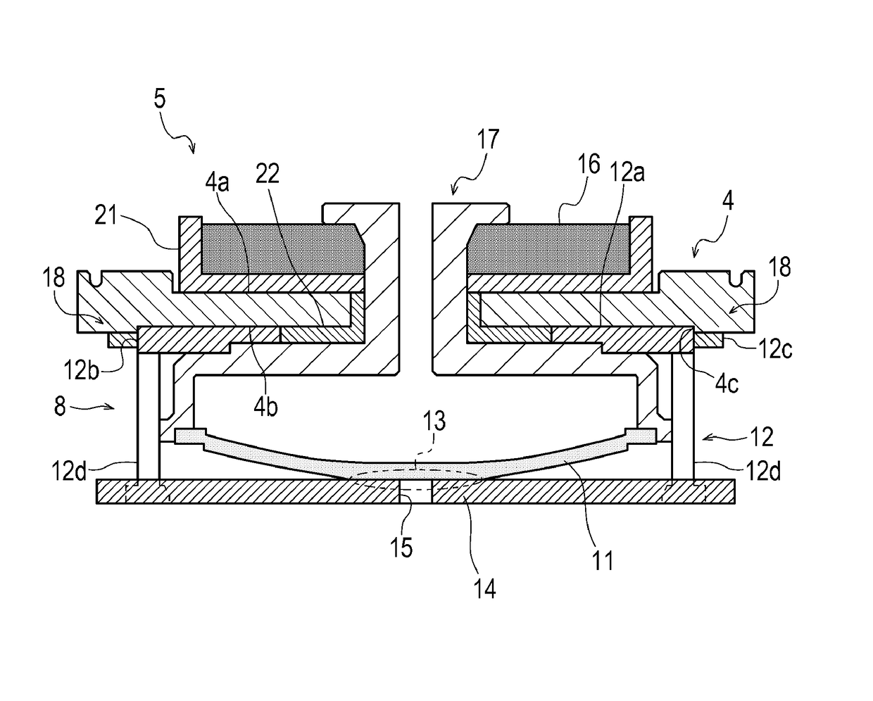
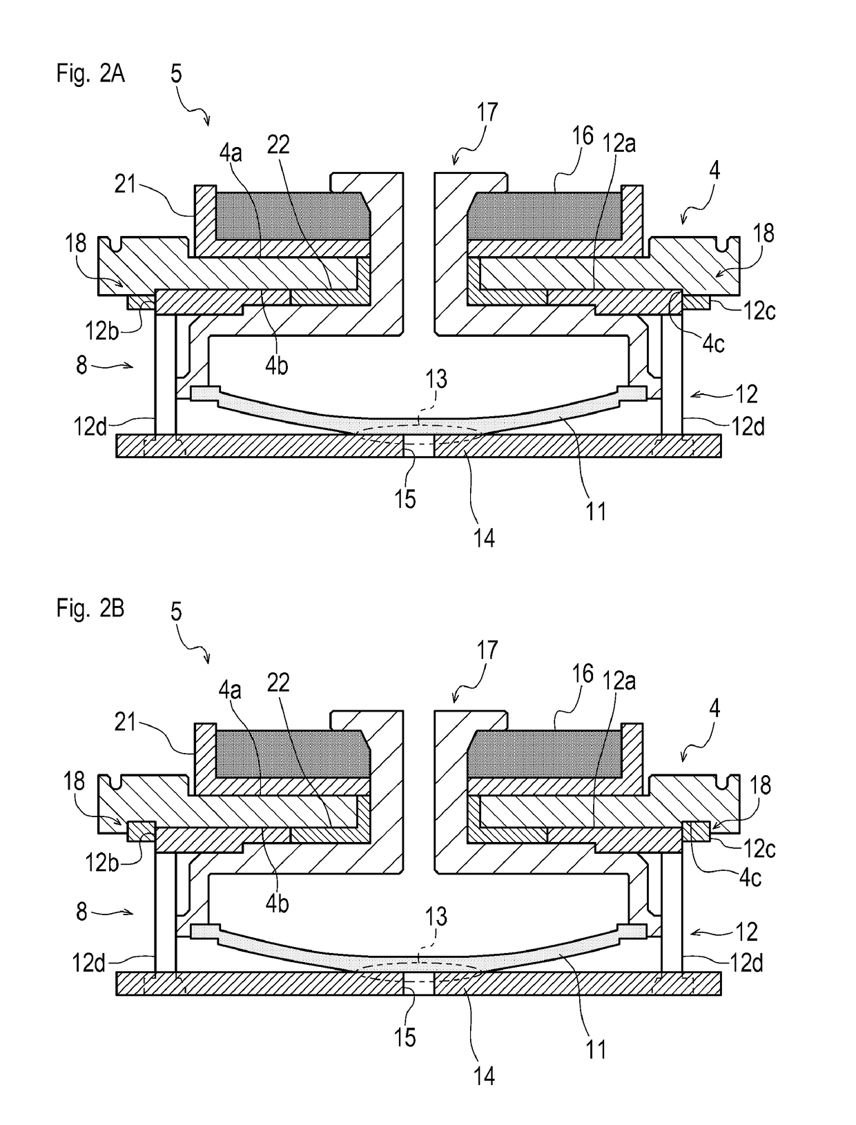
[0047]FIG. 2A shows a structure around the positive electrode 5 in the secondary battery 1.

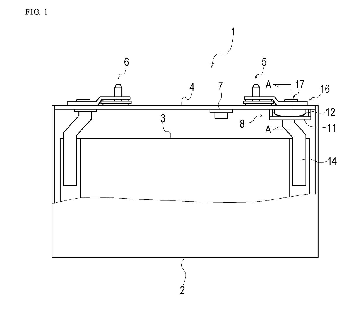
[0048]As shown in FIG. 2A, the positive electrode 5 of the secondary battery 1 according to the first embodiment includes the current interrupt device 8 which has a reverse plate 11 acting as a diaphragm and connected to a rivet 17, and the holder 12 as an insulator for holding a collector tab 14 of the positive electrode, and which is formed by welding the reverse plate 11 to the collector tab 14 of the positive electrode with a predetermined strength at a welded portion 13. The positive electrode terminal 16 is placed to come in contact with one face (upper face 4a) of the sealing plate 4, the holder 12 is placed to come in contact with the other face (lower face 4b) of the sealing plate 4, the positive electrode terminal 16 and the holder 12 are joined to the sealing plate 4 by the rivet 17, and the positive electrode terminal 16 and the collector tab 14 of the positive electrode are electr...

second embodiment

[0073]FIG. 2B shows the structure around the positive electrode 5 in the secondary battery 1.

[0074]As shown in FIG. 2B, in the positive electrode 5 in the secondary battery 1 according to the second embodiment, protrusions 12c formed at the holder 12 are formed to protrude from a main body 12a of the holder 12 in the direction in which the sealing plate 4 and the holder 12 are stacked, and the recess 4c is formed by partially digging the lower face 4b. In the embodiment, not the entire main body 12a of the holder 12 but only the protrusions 12c are fitted in the recess 4c in the embodiment.

[0075]In other words, in the secondary battery 1 according to the one embodiment of the present invention, the entire main body 12a of the holder 12 may be fitted in the recess 4c as shown in FIG. 2A, or alternatively, only the protrusions 12c formed at the main body 12a of the holder 12 may be fitted in the recess 4c as shown in FIG. 2B.

[0076]FIGS. 5 and 6 show other examples of a manner of formi...


PUM

PropertyMeasurementUnit
frequencyaaaaaaaaaa
welding strengthaaaaaaaaaa
internal pressureaaaaaaaaaa

Abstract

Disclosed is a secondary battery capable of preventing damage to a current interrupt device caused by generation and transmission of vibration, and thereby achieving prevention of malfunction of the current interrupt device, and improvement of quality of the secondary battery. In addition, disclosed is a method of manufacturing the secondary battery. Specifically disclosed is a secondary battery, in which a positive electrode terminal is placed on the upper face of a sealing plate, a holder is placed on the lower face of the sealing plate, and the sealing plate is joined to the positive electrode terminal and the holder by a rivet. The secondary battery includes an adhered portion for adhering the holder to the sealing plate.

Description

TECHNICAL FIELD[0001]The present invention relates to a technique for a secondary battery and a method of manufacturing the secondary battery.BACKGROUND ART[0002]A secondary battery generally includes a CID (Current Interrupt Device) in case of excessive increase in internal pressure.[0003]There is a known current interrupt device which includes a reverse plate acting as a diaphragm and a holder as an insulator for holding the reverse plate, the reverse plate being welded to a collector tab of a positive electrode at a predetermined welding strength.[0004]In such a current interrupt device, when internal pressure of a secondary battery increases, the reverse plate pushed by electrolyte solution is reversed and separated from the collector tab (conduction is blocked) to interrupt electric current. For this purpose, in the current interrupt device with this structure, the welding strength between the collector tab and the reverse plate is set to a value lower than joint strengths betw...

Claims


Application Information

Patent Timeline
Patent Type & Authority Patents(United States)
IPC IPC(8): H01M2/34H01M10/04H01M2/06H01M2/30H01M50/176H01M50/55H01M50/553H01M50/567
CPCH01M2/345H01M2/06H01M2/30H01M10/04H01M2200/20Y10T29/49114H01M50/578H01M50/176H01M50/553H01M50/567H01M50/55Y02E60/10Y02P70/50H01M10/049
Inventor NAKAMURA, KOSUKEWADA, NAOYUKIMURATA, ICHIROOKADA, YUKIHIRO
Owner TOYOTA JIDOSHA KK
Learn More