Motion sensor device and use thereof

a motion sensor and motion sensor technology, applied in the field of motion sensor devices, can solve the problems of undesirable false activation, limited detection area, undesirable properties of the motion sensor, etc., and achieve the effect of convenient handling

Active Publication Date: 2017-09-19
STEINEL
View PDF0 Cites 14 Cited by
  • Summary
  • Abstract
  • Description
  • Claims
  • Application Information

AI Technical Summary

Benefits of technology

[0006]The present invention therefore is based on the objective of realizing a motion sensor device such that it is more user friendly, can be easily handled and, in particular, arbitrarily and flexibly configured by untrained or easily trainable users, wherein it should also be possible, in particular, to adjust detection regions that are not realized symmetrical—e.g. referred to a center axis protruding into the detection region—and to configure complex detection regions or detection regions that cannot be simply mapped with straight lines.
[0013]According to an advantageous enhancement of the invention, the function of the interface unit and adjustments thereon or thereby also make it possible for the boundary to feature in the plane of motion a first arcuate section with a first arc shape and (at least) one second arcuate section with a second arc shape that differs from the first arc shape. These arc shapes are preferably connected to one another in order to form a continuous curve, wherein this has the advantageous effect that the inventive flexible variability can be realized in the detection region frontally as well as laterally in an easily reproducible and easily implementable fashion. In this context, it is furthermore preferred to sectionally realize these respective arc shapes in an arcuate, elliptical or paraboloidal fashion; these arc shapes not only allow a mathematically simple constructive design of the geometry (with correspondingly reduced demands on a computer elevation during comparison operations within the inventive comparing means), but these shapes can also be easily reproduced and arranged by a user and correspond to many actual geometric circumstances at an operating site.
[0015]In the context of the invention, it is on the one hand advantageous and also preferred to describe a detection region, which can be suitably defined by adjusting a maximum axial distance (e.g., in accordance with the above-described preferred embodiments), by means of curves or (interconnected) curved paths, but it is alternatively or additionally also preferred to realize the boundary of the plane of motion (or a section of this boundary) linearly by suitably configuring the interface unit. This in turn makes it possible to realize such a boundary rectangular, in the form of a polygon or another structure with linear sections (having the same or different lengths); in a mixed variation with the above-described exemplary embodiment with curved shapes, these boundaries may also be realized sectionally curved with the cited exemplary functional shapes.

Problems solved by technology

However, devices of this type, which are based on the infrared principle, also have certain disadvantages; first of all, an effective detection region, i.e. a region defined by the maximum distance of a detection object with a certain minimum size to be reliably detected, is limited due to the principle used.
In addition, infrared-based sensors can be affected by environmental influences such as, e.g., changes in the temperature and / or light conditions and therefore cause potentially undesirable false activations.
However, this high-frequency technology is—due to the principle used—also associated with certain disadvantages; a detector sensitivity (and therefore also a motion detection sensitivity) is dependent on the (moving) direction, in which the detection object moves relative to the sensor.
In addition, the difference between a relatively small detection object moving in the vicinity of the sensor and a relatively large object moving at a greater distance from the sensor (and potentially even outside a desired detection region) is difficult to detect with such a sensor and therefore also creates problems.
Furthermore, the ability of high-frequency signals to penetrate materials leads to undesirable properties of the motion sensor; the motion sensor may, if applicable, also react to motions that take place behind a wall or similar partition and are irrelevant to a detection function.
However, the technology described in DE 10 2012 103 177 A1 is still in need of improvement with respect to its configurability and user-friendliness; for example, it is difficult for a user of such a known exterior sensor device to adjust or define a detection region in a plane of motion, which is not arcuate and radially symmetrical to the sensor housing as starting point for the sensor functionality.
This means that the known technology is also not particularly well suited for use in the field of consumer goods, in which not only low manufacturing costs, but also a simple operation, preferably without the need for instructions or user manuals, can be a critical success factor.

Method used


Image

  • Motion sensor device and use thereof
  • Motion sensor device and use thereof
  • Motion sensor device and use thereof

Examples


Embodiment Construction

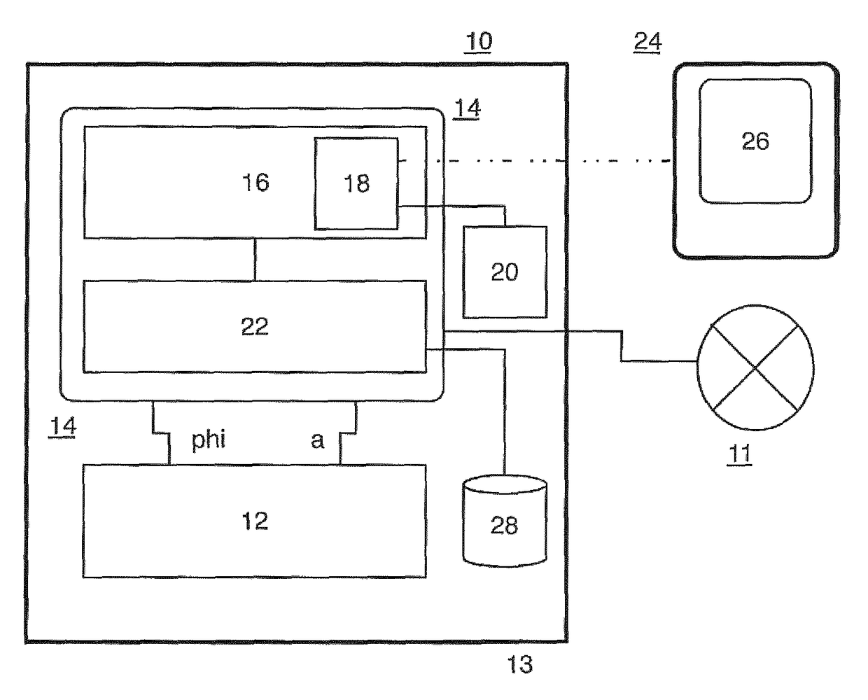
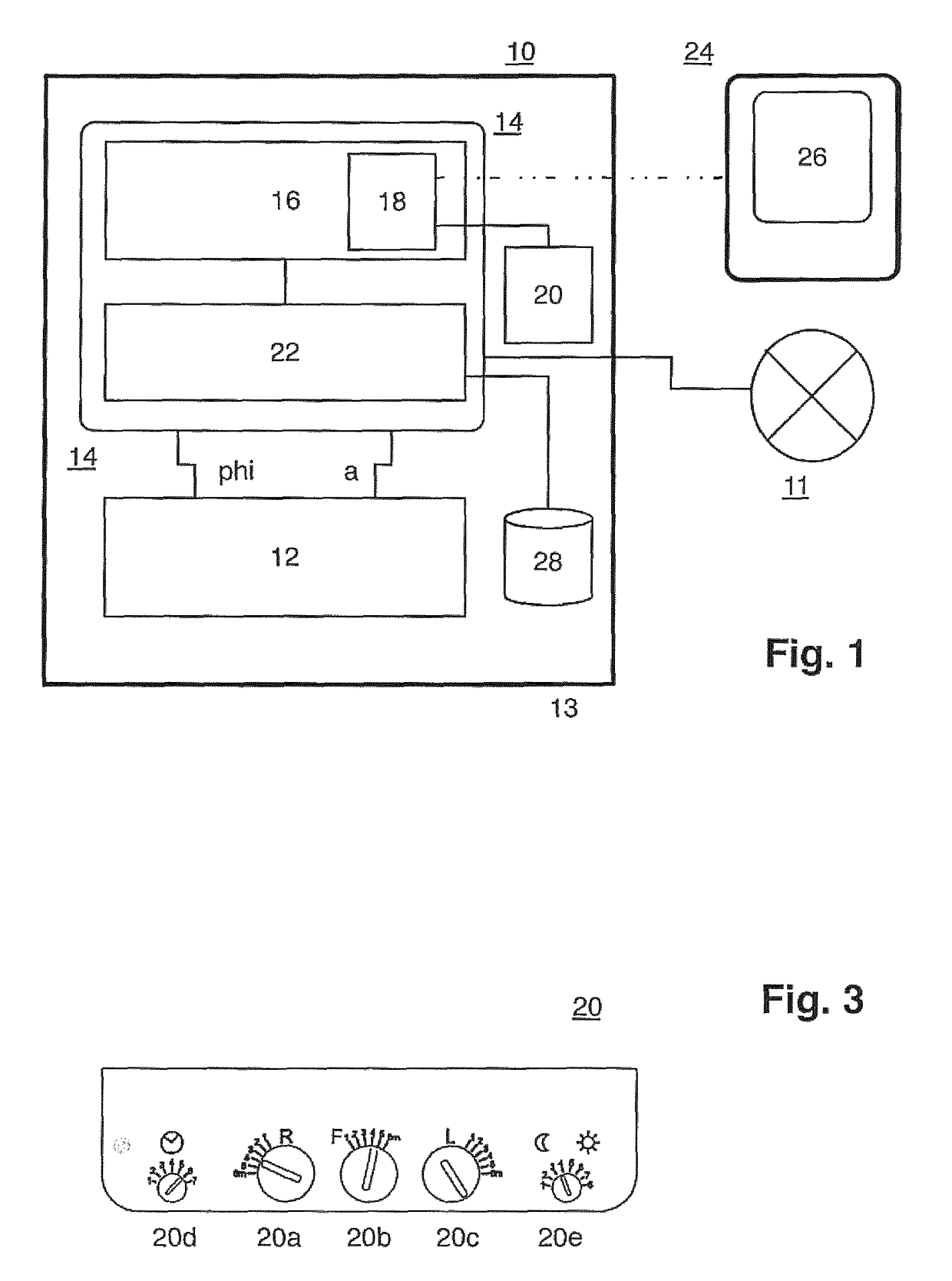
[0023]FIG. 1 shows a first preferred exemplary embodiment of a motion sensor device according to the present invention in the form of a schematic block diagram. Detector means 12 are provided in a housing, which is indicated with the border line 10 and suitably mounted on a wall, a ceiling or the like, and realized in the form of a high-frequency motion sensor device; detector means of this type in the form of high-frequency motion sensors are disclosed in DE 10 2012 103 177 A1 by the applicant, which with respect to the constructive realization of such a motion sensor device including the realization of the functional components according to FIG. 1 of this publication, the high-frequency hardware according to FIG. 2 of this publication and the signal processing functionality according to FIGS. 3, 4 of this publication, as well as the corresponding portions of the description, is incorporated into the disclosure of the present application by reference. Detector means designed in thi...


PUM


Abstract

A motion sensor device for detecting a detection object in a detection region, with detector means (12) which are arranged in a sensor housing (10) and designed for detecting motions of the detection object, as well as for generating an electronic distance signal (a) and angle signal (phi) corresponding to the detection object, wherein the distance signal (a) corresponds to an instantaneous distance of the detection object from the sensor housing (13) and the angle signal corresponds to an instantaneous position angle (phi) of the detection object in the form of an azimuth angle in a plane of motion of the detection object extending parallel to the ground surface in the installed state of the motion sensor device on a wall and signal processing and control means (14) connected downstream of the detector means are designed for activating a device (11) to be connected downstream of the motion sensor device in dependence on the distance signal and the angle signal, and wherein the signal processing and control means feature detection region determining means (16) with an interface unit (18; 20), which can be adjusted, configured and / or actuated by a user and serves for at least sectionally adjusting and / or defining a boundary of the detection region in the plane of motion, wherein the signal processing and control means feature comparing means (22), which are designed for comparing a distance signal and angle signal generated for a detection object by the detector means with data on a predefined or adjusted boundary of the detection region that can be variably defined and / or adjusted relative to the sensor housing frontally (32) and laterally (30, 34) in the plane of motion, wherein display and / or visualization means (26) are assigned to the interface unit (18) in order to optically display and / or output the boundary.

Description

BACKGROUND OF THE INVENTION[0001]The present invention relates to a motion sensor device. The present invention furthermore relates to the utilization of such a motion sensor device within a wall or ceiling light.[0002]Motion detection sensors in the form of various detection technologies and corresponding technical principles are known from the prior art, wherein a common and frequent application is the use of such a motion detection sensor for activating a light. For example, it is common practice to utilize so-called PIR (passive infrared) sensors for the motion detection in interior and exterior regions (e.g. referred to a building, on which a corresponding motion sensor device is installed either by itself or in connection with a lighting unit) and to thereby control a lighting system, wherein these sensors generate a detection signal based on detected infrared radiation in the detection region (more precisely: infrared radiation in the map of the detection region, which change...

Claims


Application Information

Patent Timeline
Patent Type & Authority Patents(United States)
IPC IPC(8): H04N5/228H04N5/14H04N5/232G06T7/20G06K9/00H04N5/225
CPCH04N5/23212G06K9/00335G06K9/00624G06T7/20H04N5/144H04N5/23296H04N2005/2255G01S7/2813G01S13/42G01S13/88H05B47/115Y02B20/40G06V40/20H04N23/69H04N23/555
Inventor MOELLER, THOMASCAPALINI, RICHARD
Owner STEINEL
Why Eureka
Try Eureka