Mattress and topper with variable and adjustable deflection areas for ultra-low pressures with postural alignment

a mattress and topper technology, applied in the field of mattresses and/or toppers, can solve the problems of reducing sleep quality, affecting sleep quality, and affecting sleep quality

Inactive Publication Date: 2017-09-26
PERFECT PRESSURE LLC
View PDF10 Cites 14 Cited by
  • Summary
  • Abstract
  • Description
  • Claims
  • Application Information

AI Technical Summary

Benefits of technology

[0037]According to a preferred embodiment, the foam mattress further comprising a second lateral channel extending from the upper surface into the middle body receiving area in the lateral direction perpendicular to the longitudi

Problems solved by technology

It is also known that mattresses can significantly affect sleep quality.
Mattress-induced discomfort caused by excessive body pressures and postural misalignment result in

Method used


Image

  • Mattress and topper with variable and adjustable deflection areas for ultra-low pressures with postural alignment
  • Mattress and topper with variable and adjustable deflection areas for ultra-low pressures with postural alignment
  • Mattress and topper with variable and adjustable deflection areas for ultra-low pressures with postural alignment

Examples


first embodiment

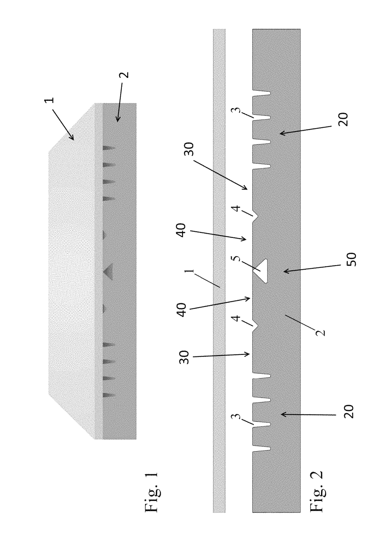
[0083]FIGS. 1 and 2 shows a first mattress base core in accordance with the invention. The mattress is formed of two foam sections with a top section 1 adapted to be affixed on a bottom base or core section 2. The base core section can be a 8″ base piece. The two sections can be glued but other methods known in the art can be used to assemble the two sections together.

Mattress Deflection Areas:

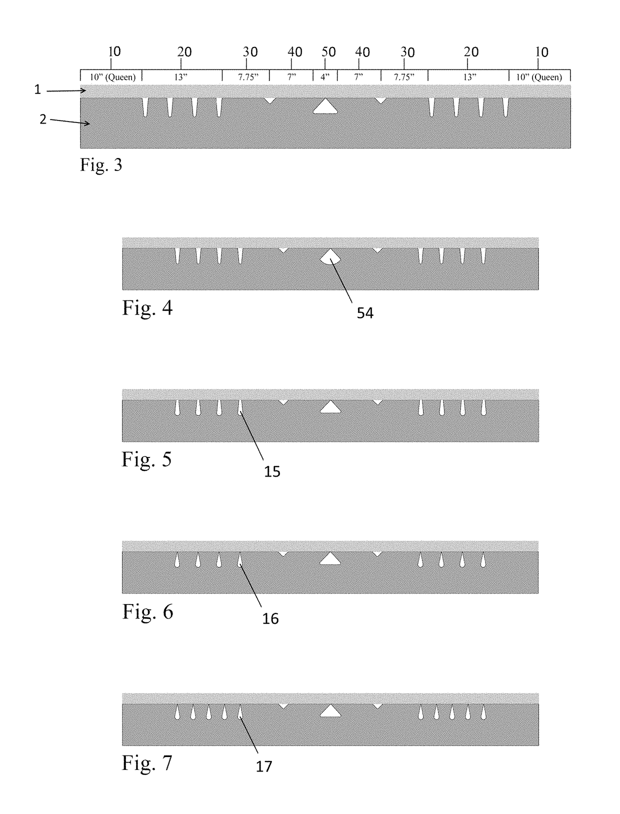
[0084]The core section 2 comprises various specific load deflection areas 20-50 which correspond to different recumbent body areas to reduce pressures to those areas while maintaining postural alignment. The areas are preferably CNC contour cut to create transversal longitudinal channels that can be either slots 3, grooves 4 or void 5.

[0085]The shoulder area 20 may comprise a series of slots 3, preferably parallel slots, for providing pressure reduction and shoulder deflection for postural alignment. A V-groove 4 can be placed between the torso area 30 and the pelvic area 40 to provide pelvic ...

embodiment 200

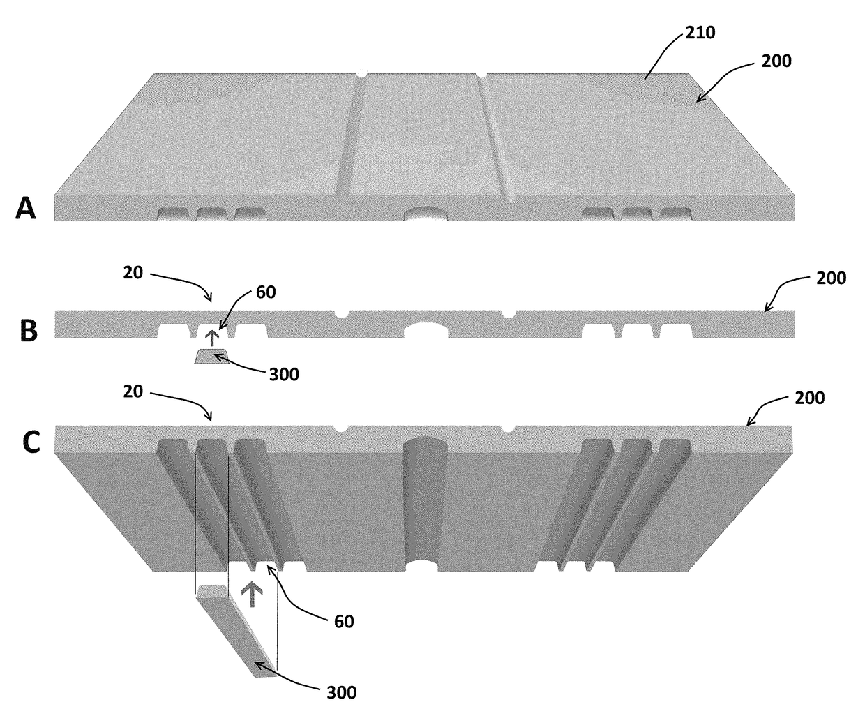
[0100]FIGS. 21 and 22 show a CNC cut foam mattress topper embodiment 200. As with all mattress embodiments, the topper is comprised of nine specialized deflection areas: head area 10, shoulder area 20, torso area 30, pelvic area 40 and trochanter area 50. The deflection channels 60 if the shoulder or low body area 20 provide shoulder elevation drop which reduces shoulder pressure by redistributing some of that pressure to the torso area 30. Torso / pelvic V-grooves 70, delimiting the torso and pelvic areas 30, 40 allows the heavier hip areas 40, 50 to deflect more than the adjacent torso area. The trochanter channel 80 extending from the lower surface reduces pressure on the greater trochanter 50.

[0101]FIGS. 23 and 24 illustrate another embodiment of the mattress 230 comprising at least one internal lateral channel 231 operatively extending between two of said first lateral channels 232 inside the mattress. In the example illustrated on FIGS. 23 and 24, the foam mattress 230 comprises...


PUM


Abstract

It is disclosed foam mattresses or toppers, and methods of using them, comprising a top surface defining lateral deflective areas thanks to structural modifications of the foam comprising a plurality of slots, grooves, voids or channels. The invention (mattresses, toppers or methods) allows controlling postural alignment while providing ultra-low mattress-body interface pressures for all body areas regardless of recumbent position. The method comprises the step of providing into a core section of the mattress a plurality of structural modifications comprising slots, and/or voids, to form transversal deflective areas into the mattress. The invention is preferably achieved by CNC (Computer Numerical Control) cutting the structural modifications (channels, slots and voids) into the mattress foam which support each area of the body. It is also disclosed mattresses or toppers in which foam inserts are kept or removed from the channels to modulate the deflections on one or both sides of the mattress.

Description

CROSS-REFERENCE TO RELATED APPLICATIONS[0001]The present patent application claims the benefits of priority of U.S. Patent Applications No. 62 / 335,959, entitled “Mattress and Topper with Variable Area Deflection Means for Ultra-low Pressures with Postural Alignment”, and filed at the U.S. Patent Office on May 13, 2016, and No. 62 / 422,154, entitled “Mattress and Topper with Variable and Adjustable Area Deflection Means for Ultra-low Pressures with Postural Alignment”, and filed at the U.S. Patent Office on Nov. 15, 2016, the content of which is incorporated herein by reference.FIELD OF THE INVENTION[0002]The present invention belongs to the field of mattresses and / or toppers and relates in particular to modifications of foam mattresses or toppers to reduce high mattress-body interface pressures while maintaining postural alignment.BACKGROUND OF THE INVENTION[0003]It is known that the quality of sleep has a significant effect on the quality of life. Multiple clinical studies have corr...

Claims


Application Information

Patent Timeline
IPC IPC(8): A47C31/12A47C27/15A47C27/14A47C27/00
CPCA47C31/123A47C27/15A47C27/148A47C27/007A47C27/144A47C27/146
Inventor TORBET, PHILIP ALANTAKEFMAN, EARL
Owner PERFECT PRESSURE LLC
Why Eureka
Try Eureka