
Miniaturized inertial measurement and navigation sensor device and associated methods

a sensor device and inertial measurement technology, applied in the field of navigation and position sensing systems, can solve the problems of complex process, inability to achieve tactical-grade performance of individual commercial-off-the-shelf (cots) micro-electro-mechanical systems (mems), and the process of creating, testing, measuring improvements, and implementing improvements is even more complex, so as to facilitate integration and improve performance.

Inactive Publication Date: 2017-09-26
JAYMART SENSORS
View PDF23 Cites 12 Cited by
  • Summary
  • Abstract
  • Description
  • Claims
  • Application Information

AI Technical Summary

Benefits of technology

The solution achieves better than tactical-grade performance levels with reduced gyro drift, noise, and improved accuracy, suitable for man-portable and UAV systems, with a compact and rugged design that simplifies the integration of additional aiding sensors and enhances navigation accuracy.

Problems solved by technology

It is known that individual commercial-off-the-shelf (COTS) micro-electro-mechanical systems (MEMS) devices do not achieve tactical-grade levels of performance when used in inertial measurement units (IMUs).
The process of improving the performance of a navigation system with new or advanced algorithms, the ability to measure and assess the improvements, and finally the ability to embed the new algorithms within the embedded software architecture and measure the improved performance is a complex process.
The process to create, test, measure the improvements, implement the improvements, and test the results to satisfy the requirements for different instruments is even more complex.
The ability to create an interface between the IMU with its embedded array of sensors, the navigation filters, multiple sensors that aid in navigation accuracy that feed them is a major challenge.

Method used


Image

  • Miniaturized inertial measurement and navigation sensor device and associated methods
  • Miniaturized inertial measurement and navigation sensor device and associated methods
  • Miniaturized inertial measurement and navigation sensor device and associated methods

Examples


Embodiment Construction

[0030]The present invention will now be described more fully hereinafter with reference to the accompanying drawings, in which preferred embodiments of the invention are shown by way of example only. This invention may be embodied in many different forms and should not be construed as limited to the embodiments set forth herein. Rather, these embodiments are provided so that this disclosure will be thorough and complete, and will fully convey the scope of the invention to those skilled in the art.

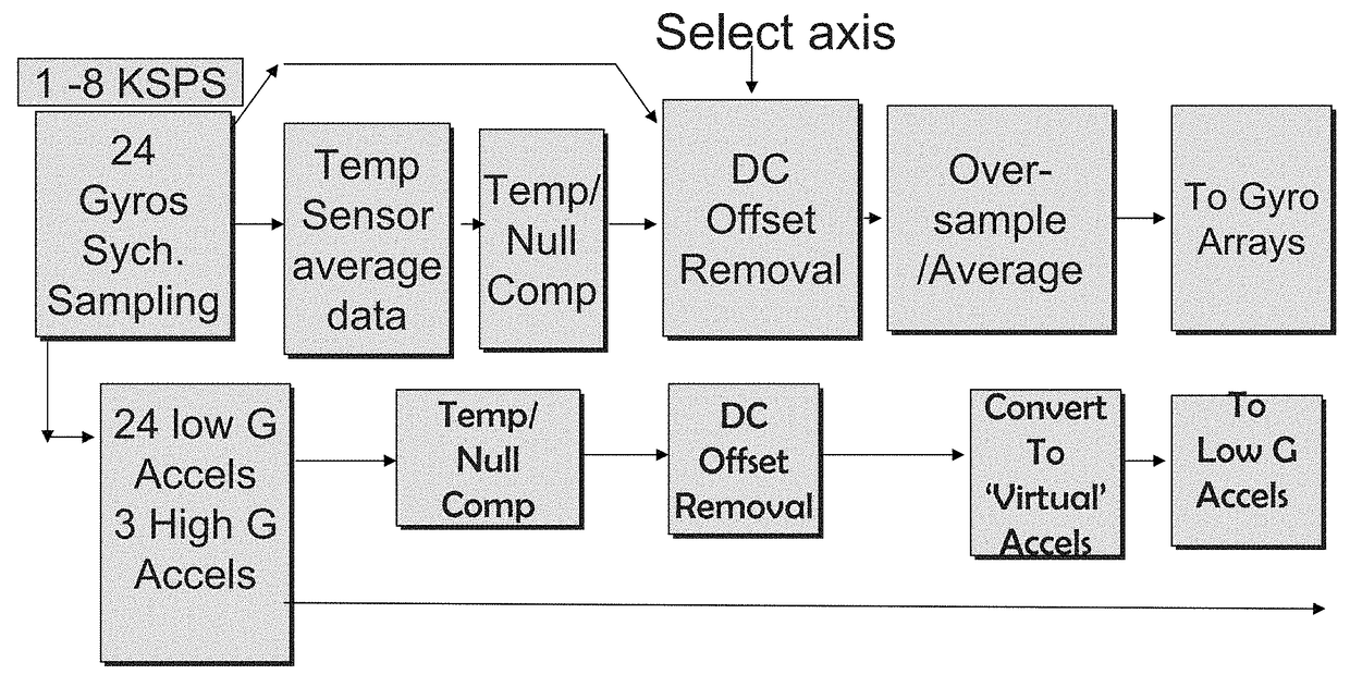
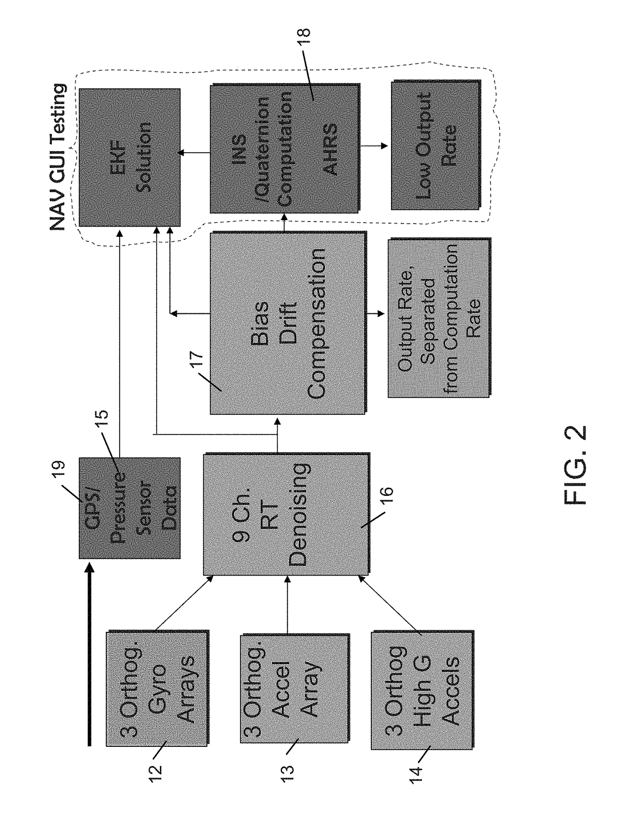
[0031]A description of embodiments of the present invention, including preferred embodiments by way of non-limiting example, will now be presented with reference to FIGS. 1-33.

[0032]The present invention is directed to a miniature IMU / INS module 10 comprising multiple sensors, algorithms, and a rugged assembly package to realize requirements of challenging technical fields of use. The invention has achieved real-time operation of a set of algorithms in the module 10. Accurate navigation tra...


PUM

PropertyMeasurementUnit
poweraaaaaaaaaa
frequencyaaaaaaaaaa
temperatureaaaaaaaaaa

Abstract

A miniaturized inertial measurement and navigation sensor device and a flexible, simplified GUI operating in real time are provided to create an optimum IMU / INS. The IMU includes multiple angle rate sensors, accelerometers, and temperature sensors to provide stability device. A navigation GUI tests algorithms prior to embedding them in real-time IMU hardware. MATLAB code is converted to C++ code tailored for real-time operation. Any point in the algorithm suite structure can be brought out as a data channel to investigate the pattern of operation. The data channels permit zooming in on the algorithm's operation for the open-loop angle, velocity and position drift measurements for bias-compensated channels. The GUI can be used to verify results of an extended Kalman filter solution as well as the implementation of the real-time attitude and heading reference system. When the code has been verified, it is compiled and downloaded into a target processor.

Description

CROSS-REFERENCE TO RELATED APPLICATIONS[0001]This application is a Continuation of U.S. patent application Ser. No. 13 / 149,124, having filing date of May 31, 2011 which itself claims priority to Provisional Patent Application Ser. No. 61 / 349,543, having filing date of May 28, 2010. The disclosures of which are hereby incorporated by reference in their entirety and all commonly ownedFIELD OF THE INVENTION[0002]The present invention relates to systems and methods for navigation and position sensing, and, more particularly, to miniaturized devices for performing inertial measurement and inertial navigation sensing.DESCRIPTION OF RELATED ART[0003]It is known that individual commercial-off-the-shelf (COTS) micro-electro-mechanical systems (MEMS) devices do not achieve tactical-grade levels of performance when used in inertial measurement units (IMUs). The process of improving the performance of a navigation system with new or advanced algorithms, the ability to measure and assess the imp...

Claims


Application Information

Patent Timeline
Patent Type & Authority Patents(United States)
IPC IPC(8): G01C19/00G01C19/02G01P15/14G01K13/00
CPCG01C19/02G01P15/14G01K13/00G01C21/165
Inventor TANENHAUS, MARTIN E.
Owner JAYMART SENSORS
Learn More