Method and apparatus for determining the position of a motor-driven actuating part

a technology determining the position of motor-driven actuating parts, which is applied in the direction of electrical/magnetically converting sensor output, measuring devices, instruments, etc., can solve the problem of increasing the uncertainty of the absolute position calculated therefrom

Active Publication Date: 2017-09-26
CONTINENTAL AUTOMOTIVE GMBH
View PDF25 Cites 4 Cited by
  • Summary
  • Abstract
  • Description
  • Claims
  • Application Information

AI Technical Summary

Benefits of technology

[0015]Since the uncertainty of the position which is newly determined from the correlation function can depend strongly on the profile of the characteristic curves used, it is advantageous if an uncertainty value is determined from the correlation function and is assigned to the position determined from the same correlation function. For this purpose it is advantageous if the correlation unit of the apparatus according to the invention is configured to determine an uncertainty value which is provided for transmission to the averaging unit together with the difference in position. Other possibilities, such as an uncertainty value which is assumed to be constant or an uncertainty value which is estimated from other parameters, are indeed possibly easier to determine, but would at any rate have to be conservative estimates since, i.e. they would over-estimate the uncertainty value of the determined position and therefore adversely affect the position determination.
[0016]In addition to the combination of the position values it is advantageous if the uncertainty values of the two positions are also combined and an uncertainty value of the current position is determined from the uncertainty value of the newly determined and the last valid position. Typically, the resulting uncertainty value here is lower than the two original uncertainty values, which reflects the gain in information as a result of the combination of the position values. For this reason it is advantageous if the averaging unit is configured to process a position uncertainty value which is made available by the position tracker, and an uncertainty value of the position determination.
[0017]In order to determine the corrected position, the positions from the position tracker and the position-measuring unit are preferably each taken into account in an inversely proportional fashion with respect to their uncertainty value. This easily ensures that that value with the relatively high level of uncertainty is taken into account to a lesser degree than that value with a relatively low level of uncertainty. The values which are taken into account are accordingly weighted with the reciprocal value of the respective uncertainty value. A special case which occurs here is the situation of a perfectly known value, for example owing to re-initialization at a mechanically precisely defined reference position, which value therefore cannot be influenced by a value determined from the measuring unit, since said value has an uncertainty value of zero and therefore has, as it were, an infinite influence or an infinite weighting.
[0020]In order to make available a continuously updated position of the actuating part between the absolute position determinations it is advantageous if the position tracker is connected to a position memory in order to detect changes in position and perform updating. The position of the actuating part is tracked by a method which is (slightly) subject to errors, wherein the uncertainty value of the current position is increased in the event of a change in position. This can involve, for example, ripple counting or the evaluation of the signals of a Hall sensor. The uncertainty values of independent measurements (such as, in fact, ripple counting or the Hall sensor) are usually easily added, with the result that although the current position can be estimated after a plurality of changes in position, the associated uncertainty value increases with an increasing number of relative position measurements.

Problems solved by technology

(1) On the one hand there are counting methods which are capable of precisely detecting the position always and under all given peripheral conditions. This is usually carried out by means of a magnet wheel attached to the motor shaft, in conjunction with two Hall sensors. The two Hall sensors permit the rotation of the motor to be determined and the rotational direction to be detected.
(2) On the other hand, there are position-determining methods or position-tracking methods which can determine the position but, under certain external circumstances, cannot avoid slight errors in the position-determining process in a system-immanent fashion. Such methods include 1-Hall position counters and, in particular, sensorless methods which infer the position from, for example, the current ripple of the commutator current of a DC motor. Such position-determining processes which are subject to errors make regular correction of the position necessary. This is carried out by means of devices for measuring positions, such as, for example, an initialization process.
Since every change in position is subject to uncertainty, the uncertainty of the absolute position calculated therefrom increases with the number of changes in position.

Method used


Image

  • Method and apparatus for determining the position of a motor-driven actuating part
  • Method and apparatus for determining the position of a motor-driven actuating part
  • Method and apparatus for determining the position of a motor-driven actuating part

Examples


Embodiment Construction

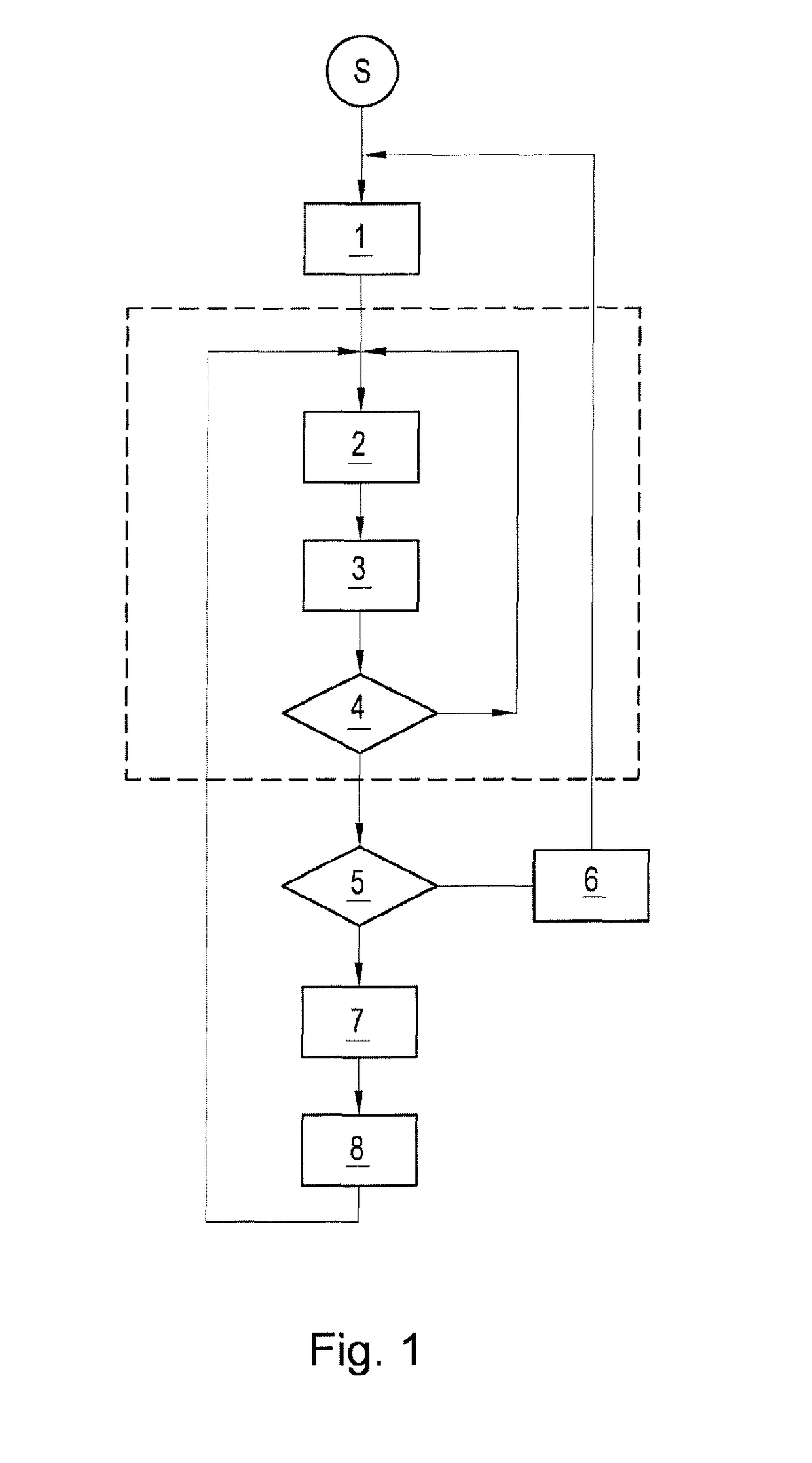
[0025]The method illustrated in FIG. 1 begins after a start S with initialization 1 of the position counting or of the position tracking. Here, both the reference position and the uncertainty value of the reference position are initialized with zero. Before the coming movement of the actuating part, the exact position thereof is therefore known. As soon as the actuating part is used, for example if a window lifter or a sunroof is activated, a change 2 in position takes place. In order to be able to make an estimation of the current position after the change 2 in position, the change 2 in position is tracked by a suitable method 3. The tracking method 3 adapts the current counting position on the basis of the recorded change 2 in position and at the same time increases the uncertainty value thereof in accordance with the uncertainty value which is to be provided for the detection of the change in the method 3 used. As long as no new initialization is triggered, the steps of the chang...


PUM


Abstract

A method and apparatus for determining the position of a motor-driven actuating part, in particular a window, a sliding roof, a boot lid, a sliding door or a seat, wherein a current position is determined and, in order to determine the current position, a position newly determined for this purpose is taken into account in conjunction with a last valid position, wherein the current position is selected to be between these two positions and closer to that position which has a comparatively lower uncertainty.

Description

CROSS REFERENCE TO RELATED APPLICATIONS[0001]This application is the U.S. National Phase Application of PCT International Application No. PCT / EP2013 / 066172, filed Aug. 1, 2013, which claims priority to German Patent Application No. 10 2012 215 214.8, filed Aug. 28, 2012, the contents of such applications being incorporated by reference herein.FIELD OF THE INVENTION[0002]The invention relates to a method for determining the position of a motor-driven actuating part, in particular of a window, of a sunroof, of a rear lid, of a convertible top system, of a sliding door or of a seat, wherein a current position correction value is determined by measuring the position, and an apparatus for carrying out the method with a position tracker (counter) and a position-measuring unit.BACKGROUND OF THE INVENTION[0003]It is necessary to determine the position of motor-driven actuating parts, in particular in the case of closing parts such as window lifters, sunroofs or sliding doors in motor vehicl...

Claims


Application Information

Patent Timeline
Patent Type & Authority Patents(United States)
IPC IPC(8): G01D5/14G01D5/244
CPCG01D5/142G01D5/2449G01D5/24476
Inventor MORAWEK, ROMAN
Owner CONTINENTAL AUTOMOTIVE GMBH
Why Eureka
Try Eureka