System and method for calibration of echo sounding systems and improved seafloor imaging using such systems

a sounding system and echo technology, applied in the field of system and method for calibration of echo sounding systems and improving seafloor imaging using such systems, can solve the problems of limiting the ability to achieve calibration, increasing the number of soundings, and limiting the quantitative error minimization approach of bjorke, so as to achieve accurate calibration and high sensitivity.

Active Publication Date: 2017-09-26
ORANGE DANIEL L
View PDF9 Cites 1 Cited by
  • Summary
  • Abstract
  • Description
  • Claims
  • Application Information

AI Technical Summary

Benefits of technology

[0008]The present invention addresses the noise limitations of the prior art by providing a method of visualizing static biases with a high level of sensitivity. Using bathymetric grids visualized using standard color-coded or grey scale images generated by a conventional echo sounding system, the inventive method calculates and displays a difference surface from the seafloor as surveyed by the same vehicle in two different directions, i.e., reciprocal survey lines, over a feature on the seafloor. The difference grid is created by subtracting the depths of all areas of the seafloor that are common from one survey line from the second. If the position and orientation systems are perfectly calibrated, the resulting difference surface will be a null (zero height) surface, producing an image that is uniform across the seafloor area. However, if any part of the orientation system has a static bias that should be corrected, the difference surface will show a pattern, with different patterns indicative of the different components that need to be corrected. By using the power of the human eye, and the pattern recognition power of the human brain, a user can “see through” noise to recognize a diagnostic pattern, thereby allowing the user to iterate toward a more accurate calibration than can be achieved with prior art methods alone.
[0009]The present invention can be used as a Quality Control (QC) tool to test the quality of an echo sounder's calibration. If all of the static bias corrections to the orientation system are perfect, the difference surface of two survey lines acquired in different directions over a feature will be a null (zero height) surface. Any deviation from a perfect calibration will result in a difference pattern. The present invention thus provides a powerful QC aid to confirm a calibration obtained by either a Patch Test or a Quantitative “automatic” correction.
[0015]In a further aspect of the invention, a method is provided for increasing the resolvability of an echo sounding system by acquiring multiple survey lines to produce overlapping swaths of seafloor data. Adjacent survey lines of the multiple survey lines may have a line offset that is less than a swath width. Alternatively, or in combination, the multiple survey lines may be acquired on multiple different headings to generate overlapping swaths of seafloor data. The method may further comprise acquiring the multiple survey lines at reduced acquisition speed to increase the sounding density along-track. The seafloor bathymetric data may be binned at progressively smaller bin sizes with progressively more overlap to further improve resolvability. The seafloor backscatter data may be mosaiced at progressively smaller pixel sizes with progressively more overlap to further improve resolvability.
[0016]Still another aspect of the invention provides a method for locating an object of interest on the seafloor using an echo sounding system, where the method comprises acquiring multiple survey lines to produce overlapping swaths of seafloor data. Adjacent survey lines of the multiple survey lines may have a line offset that is less than a swath width. Alternatively, or in combination, the multiple survey lines may be acquired on multiple different headings to generate overlapping swaths of seafloor data. The method may further comprise acquiring the multiple survey lines at reduced acquisition speed to increase the sounding density along-track. The seafloor bathymetric data may be binned at progressively smaller bin sizes with progressively more overlap to further improve resolvability. The seafloor backscatter data may be mosaiced at progressively smaller pixel sizes with progressively more overlap to further improve resolvability.

Problems solved by technology

Both the patch test and the quantitative error minimization approach of Bjorke are limited by the noise inherent to any acoustic surveying system.
This noise will limit the ability to achieve a calibration because the user reaches a point at which the size of the correction is less than the scale of the scatter of the soundings.
A wider corridor, which increases the number of soundings, also increases the number of noisy soundings.
A quantitative correction will also be limited by soundings.

Method used


Image

  • System and method for calibration of echo sounding systems and improved seafloor imaging using such systems
  • System and method for calibration of echo sounding systems and improved seafloor imaging using such systems
  • System and method for calibration of echo sounding systems and improved seafloor imaging using such systems

Examples


Embodiment Construction

[0032]For purposes of the present description, the following definitions will be used:

[0033]“Vehicle” means any ship, towfish, autonomous underwater vehicle (AUV), submarine, boat, barge, raft, etc. that can be used to acquire echo sounding data.

[0034]“Seafloor” means the ocean floor or the bottom of any body of water, natural or man-made (lake, river, stream, harbour, ocean, canal, marina, etc.)

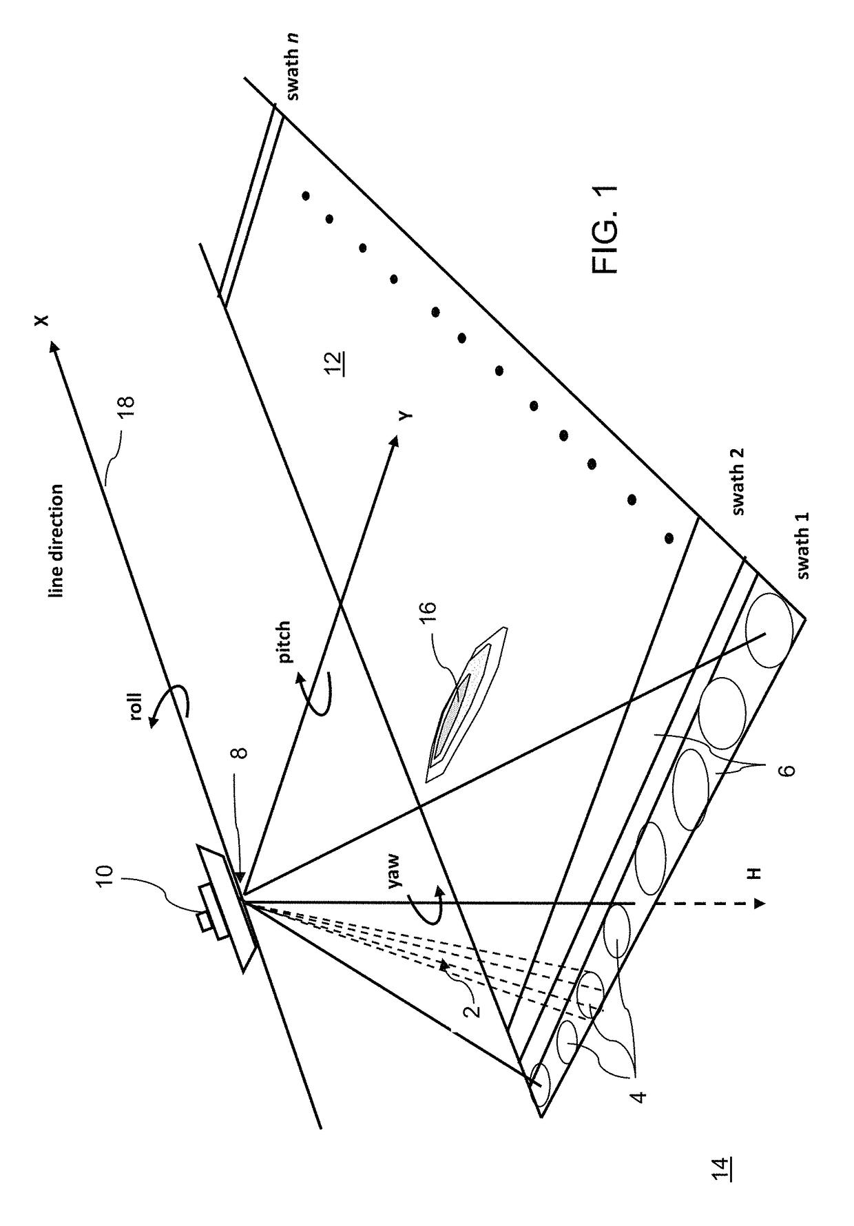
[0035]FIG. 1 illustrates the basic elements of an echo sounding measurement. A vehicle 10 moves along a direction X while making echo sounder measurements of the seafloor 14. In a multibeam technique, an acoustic array mounted parallel to the length of the ship transmits acoustic energy in a fan-shaped pattern 2, narrow along-track and broad across-track (swath 1). A second acoustic array, perpendicular to the first and mounted athwartship, receives acoustic signals from a fan-shaped area that is narrow across-track, and elongate along-track. The area of the seafloor in common between the tr...


PUM


Abstract

A system and method are provided for visualizing an offset in static parameters in an echo sounding system by generating a difference grid by subtracting a first survey line from a second survey line to determine difference values at each point in the grid; and displaying the difference grid on a display device, where the difference values are represented on a visual scale. The difference values may be used to calibrate the echo sounding system or check the quality of the calibration of an echo sounding system.

Description

RELATED APPLICATIONS[0001]This application is a 371 national stage filing of International Application No. PCT / US2014 / 029597, filed Mar. 14, 2014, which claims the benefit of U.S. Provisional Application No. 61 / 786,521, filed Mar. 15, 2013, the contents of which are incorporated herein by reference in its entirety.FIELD OF THE INVENTION[0002]The present invention relates to a system and method for improving the calibration and / or checking the calibration of acoustic imaging systems for mapping the floor of a body of water.BACKGROUND OF THE INVENTION[0003]Echo sounding systems, which are widely used for underwater imaging, work by transmitting a sound pulse or “ping” at a specific frequency, and then receiving that same pulse through a receiver. The received signal is input into a computer processor that determines how long it takes to receive the returning pulse. This delay is translated into depth. The processing system assigns a color range or grey scale for depth to create a 2D o...

Claims


Application Information

Patent Timeline
Patent Type & Authority Patents(United States)
IPC IPC(8): G01V1/38G01S7/52G01S15/89G01S15/02G01S7/62G01S15/87
CPCG01S7/52004G01S7/6263G01S15/025G01S15/87G01S15/89G01S15/86
Inventor ORANGE, DANIEL L.
Owner ORANGE DANIEL L
Why Eureka
Try Eureka