
Blade device for a mixing propeller and the application thereof

a technology of blade device and propeller, which is applied in the direction of mixing, chemistry apparatus and processes, and mixers, etc., can solve the problems of inconvenient use, large size of mixers, and inability to meet the requirements of wastewater treatment that requires long operation duration and high stability

Active Publication Date: 2017-10-03
JIANGSU PROVINCIAL ACAD OF ENVIRONMENTAL SCI
View PDF10 Cites 0 Cited by
  • Summary
  • Abstract
  • Description
  • Claims
  • Application Information

AI Technical Summary

Benefits of technology

The present invention provides a blade device for a mixing propeller that can effectively prevent precipitation of activated sludge flocs in the biopool and achieve desirable flow state of the liquid mixture within small-sized channels. The blade device has advantages such as being convenient for anticorrosive processing, simple in structure, stable during operation, easy for maintenance and low in manufacture cost. The blade device can provide both propelling and uplifting functions to the liquid mixture and can be used at a lower flow rate to improve the removal efficiency of pollutants.

Problems solved by technology

Besides, once being manufactured out, these mixers are usually considerably huge.
Therefore, they are not suitable for being used in the wastewater treatment that requires long operational duration and high stability.

Method used


Image

  • Blade device for a mixing propeller and the application thereof
  • Blade device for a mixing propeller and the application thereof
  • Blade device for a mixing propeller and the application thereof

Examples


embodiment 1

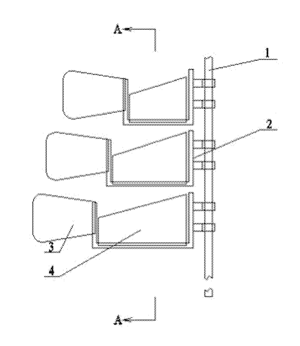
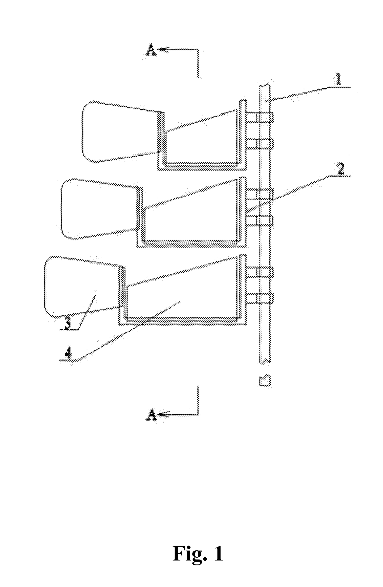
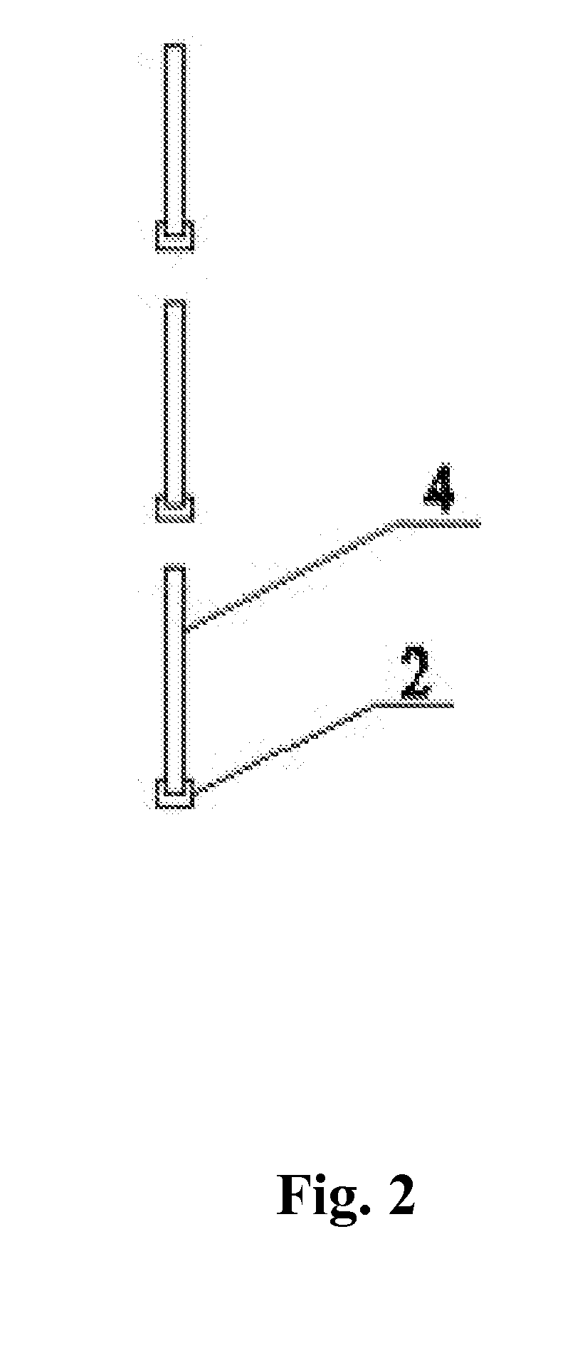
[0026]As is shown in FIG. 1 and FIG. 2, the blade device for the low-speed mixing propeller comprises a rocking shaft 1 and three fixing grooves 2 secured on the rocking shaft 1. As is shown in FIG. 3, each fixing groove 2 consists of a horizontal section 21 and a vertical section 22. One end of the horizontal propelling flexible blade 3 is inserted in the vertical section 22 of the fixing groove 2, and the other end of the horizontal propelling flexible blade 3 can swing back and forth; one end of the vertical uplifting flexible blade 4 is inserted in the horizontal section 21 of the fixing groove 2, and the other end of the vertical uplifting flexible blade 4 can swing back and forth. During the operation, the horizontal propelling flexible blade 3 can propel the liquid mixture to the pre-set flow rate while the vertical uplifting flexible blade 4 can uplift the liquid mixture so that the activated sludge flocs contained in the liquid mixture are brought upward, which consequently...

embodiment 2

[0031]The swinging frequency of the blade device is slowed down so that the impact of lowering down the flow rate on the efficiency of denitrification can be verified. The experiment was conducted using the blade device disclosed in Embodiment 1 and the blade device was also placed in the activated sludge channel of a biopool as was done in Embodiment 1. Control the flow rate of the liquid mixture in the channel around 0.1 m / s, and increase the number of blade devices distributed in the channel accordingly; during the 2 months' experiment, no floating piece of dead sludge was found, besides, the experiment showed even better efficiency in denitrification (the efficiency of denitrification increased at least 10%). However, though the efficiency of pollutant removal will increase when the flow rate of the liquid mixture turns lower, the number of the blade devices distributed in the channel must be increased accordingly, which consequently increases the operational cost. Therefore, th...


PUM


Abstract

A blade device for a mixing propeller has a rocking shaft and a plurality of blade units. The blade unit is made of a flexible material and is installed on the rocking shaft via a fixing groove. The blade unit includes a horizontal propelling flexible blade and a vertical uplifting flexible blade. The fixing groove has a horizontal section and a vertical section. One end of the horizontal propelling flexible blade is inserted in the vertical section of the fixing groove while the other end of which is kept free so that it can swing back and forth. One end of the vertical uplifting flexible blade is inserted in the horizontal section of the fixing groove while the other end of which is kept free so that it can swing back and forth.

Description

THE FIELD OF THE INVENTION[0001]The present invention relates to devices for wastewater treatment, specifically to a blade device and its application in a mixing propeller that is used for treating the low-speed liquid mixture.TECHNICAL BACKGROUND[0002]Currently, in the field of wastewater treatment, submersible mixers are widely utilized in both China and most of other countries for industrialized-scale treatment of liquid mixture. The blades designed for these submersible mixers are all made of rigid material. As drive motors of these submersible mixers were installed below the liquid surface, the designing and manufacturing processes of these mixers require sophisticated techniques. Besides, once being manufactured out, these mixers are usually considerably huge. As to those experimental-use small mixers, like those designed out of the same principles for industrialized production, they also present a variety of shortcomings such as inconvenience for being placed in the channel o...

Claims


Application Information

Patent Timeline
Patent Type & Authority Patents(United States)
IPC IPC(8): B01F11/00
CPCB01F11/0091B01F11/0088B01F2215/0052B01F31/445B01F31/449B01F2101/305
Inventor XU, MINGLIU, WEIJINGTU, YONGWU, HAISUO
Owner JIANGSU PROVINCIAL ACAD OF ENVIRONMENTAL SCI
Learn More