Cantilever connecting structure for roots pump or screw pump

A connection structure, screw pump technology, applied in the direction of pumps, pump components, rotary piston pumps, etc., can solve the problems of runout, the inability of the rotor to mesh, and meet the stiffness, etc., to reduce the requirements of machining, reduce the risk of deviation, increase The effect of locking force

Active Publication Date: 2021-11-05
兑通真空技术(上海)有限公司
View PDF7 Cites 0 Cited by
  • Summary
  • Abstract
  • Description
  • Claims
  • Application Information

AI Technical Summary

Problems solved by technology

[0006] However, the biggest problem with the use of cantilever rotors is that according to the principle of the force arm, the bearing-less end of the shaft and the rotor lacks stability. When rotating at high speed, it is easy to have a huge jump, resulting in the failure of the adjacent rotors to mesh.
Moreover, the installation method of the cantilever rotor is relatively complicated. First of all, it must meet the end face clearance and the azimuth. The more common cantilever method is a through shaft, the impeller is sleeved on the shaft, and the azimuth is ensured by a key.
At this moment, the strength of the cantilever shaft and the length of the cantilever are very critical. If the cantilever is too long, all the weight of the rotor will be loaded on the shaft, and the greater the torque will be, the beating cannot be guaranteed when rotating.
And because it is a cantilever shaft, the shaft cannot use a larger diameter to meet the rigidity
So this structure must be very unstable

Method used


Image

  • Cantilever connecting structure for roots pump or screw pump
  • Cantilever connecting structure for roots pump or screw pump
  • Cantilever connecting structure for roots pump or screw pump

Examples


Embodiment 1

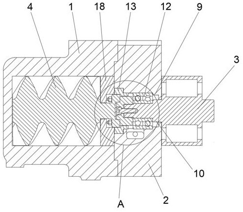
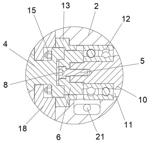
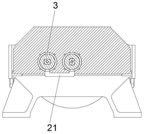
[0035] Embodiment one, such as Figure 1-10 As shown, a cantilever connection structure for a Roots pump or a screw pump includes an outer casing 1, a bearing cover 2, a drive shaft rotor 3 and a cantilever rotor 4, and one end of the drive shaft rotor 3 is connected to the drive shaft through a locking bolt 5. One side of the positioning sleeve 6 is fixedly connected, and the inner circle of the other side of the driving positioning sleeve 6 is provided with a circular boss 7, and the outer circle of the other side of the driving positioning sleeve 6 is respectively provided with bolt holes 14; the cantilever rotor 4 and The drive shaft rotor 3 is set coaxially. The cantilever rotor 4 includes a linear rotor 41, a transition cylinder 42 and a cantilever rotor positioning ring 43. One side of the linear rotor 41 is connected with the cantilever rotor positioning ring 43 through the transition cylinder 42. The cantilever The outer surface of the rotor positioning ring 43 is pro...

Embodiment 2

[0041] Embodiment 2, as a further preferred solution of Embodiment 1, a wave spring 8 is fixedly installed between the outer surface of the circular boss 7 and the inner surface of the groove 44 . Through the wave spring 8, the driving shaft rotor 3 and the driving positioning sleeve 6 can play a reverse driving force when locking, so that the locking bolt 5 of the driving positioning sleeve 6 and the thread in the bolt hole on the end face of the driving shaft rotor 3 Locking increases the locking strength and eliminates the gap, so that it will not loosen due to high-speed rotation and vibration, similar to traditional lock nuts and thrust washers. In this embodiment, the locking bolt 5 adopts an inner hexagonal bolt structure, and preferably uses a fine thread bolt, so that the effect is more obvious.

Embodiment 3

[0042] Embodiment three, such as Figure 6 As shown, as a further preferred solution of Embodiment 1, the side of the drive shaft rotor 3 close to the cantilever rotor 4 is provided with a flat key structure, and the side surface of the driving positioning sleeve 6 is provided with a flat key hole 61, and the driving positioning sleeve 6 passes through the flat key hole 61 cooperate with the flat key structure. Using the flat keyway formed by the flat key structure on one side of the drive shaft rotor 3, the drive shaft rotor 3 is inserted into the drive positioning sleeve 6, and during the rotation of the drive shaft rotor 3, the drive positioning sleeve 6 can be better driven to rotate together .


PUM


Abstract

The invention discloses a cantilever connecting structure for a roots pump or a screw pump. The cantilever connecting structure comprises an outer shell, a bearing end cover, a driving shaft rotor and a cantilever rotor, wherein the driving shaft rotor is connected with a driving positioning sleeve, and a circular boss is arranged on the driving positioning sleeve; the cantilever rotor comprises a linear rotor, a transition cylinder and a cantilever rotor positioning ring; the cantilever rotor positioning ring is fixedly connected with the driving positioning sleeve; and the cantilever rotor is sleeved with the outer shell, the bearing end cover is arranged at the outer side of the driving shaft rotor, a first step is arranged in the bearing end cover, a second step is arranged on the outer surface of the driving shaft rotor, a bearing cavity is formed between the first step and the second step, and a bearing is installed in the bearing cavity. The cantilever connecting structure overcomes the defects in the prior art, the cantilever rotor positioning ring is matched with the driving positioning sleeve, the driving positioning sleeve is matched with the driving shaft rotor, the rigidity of the cantilever rotor can be ensured, the overall performance of the cantilever rotor can be kept, the machining requirement of the cantilever rotor is greatly lowered, and embedded matching of an extended shaft and the rotor is not needed any more.

Description

technical field [0001] The invention relates to the technical field of Roots pumps, in particular to a connection structure of a cantilever shaft or a rotor using a rotor hybrid cantilever structure or a cantilever structure for Roots vacuum pumps, Roots blowers, screw vacuum pumps and multi-stage dry vacuum pumps. In particular, it relates to a cantilever connection structure for a Roots pump or a screw pump. Background technique [0002] Most of the traditional Roots vacuum pumps, Roots blowers, screw vacuum pumps and other types of multi-stage dry vacuum pumps adopt a non-cantilever structure, that is, the impeller in the pump chamber and the two ends of the shaft are respectively supported by bearings and realize rotation. . The biggest advantage of this traditional mode is that the weight of the rotor is evenly distributed on the bearings at both ends, and the bearings at both ends are fixed in the bearing cavity, so the stability of the intermediate rotor and the mini...

Claims


Application Information

Patent Timeline
Patent Type & Authority Applications(China)
IPC IPC(8): F04C2/16F04C2/12F04C15/00
CPCF04C2/16F04C2/126F04C15/00Y02P20/10
Inventor 荣易
Owner 兑通真空技术(上海)有限公司
Why Eureka
Try Eureka