
Modular assembled artificial skating rink

a technology of artificial skating and modules, applied in the direction of lighting and heating equipment, applications, roads, etc., can solve the problems of limited sports to be held only in a region, one-piece ice surface, and inability to specifically make ice in the necessary regions, so as to reduce energy consumption. the effect of substantial reduction

Inactive Publication Date: 2017-10-03
LI GUANG JING
View PDF23 Cites 2 Cited by
  • Summary
  • Abstract
  • Description
  • Claims
  • Application Information

AI Technical Summary

Benefits of technology

[0005]To overcome the defects described above, the present invention provides a modular assembled artificial skating rink which can separately make ice on different regions. The different regions on the same skating rink are assembled to meet all kinds of requirements to avoid wasting energy.
[0016]Compared with the prior art, the present invention can separately make ice on the necessary regions according to different usage requirements of the rink, and makes an ice surface with a necessary shape as required. In the process of making ice, the rink only makes ice on the necessary regions separately, and thus reduces energy consumption substantially.

Problems solved by technology

Conventional ice sports are held on an ice surface formed naturally under a cold weather condition, which limits the sports to be held only in a region with cold weather.
Although the ice-making device can make the ice surface with a reliable quality quickly, it can only make the one-piece ice surface, and cannot specifically make ice on necessary regions.
For such circumstances, it is obviously wasteful to make the whole ice surface, because the ice surface on an inner region of the annular skating track is not necessarily needed.

Method used


Image

  • Modular assembled artificial skating rink
  • Modular assembled artificial skating rink
  • Modular assembled artificial skating rink

Examples


Embodiment Construction

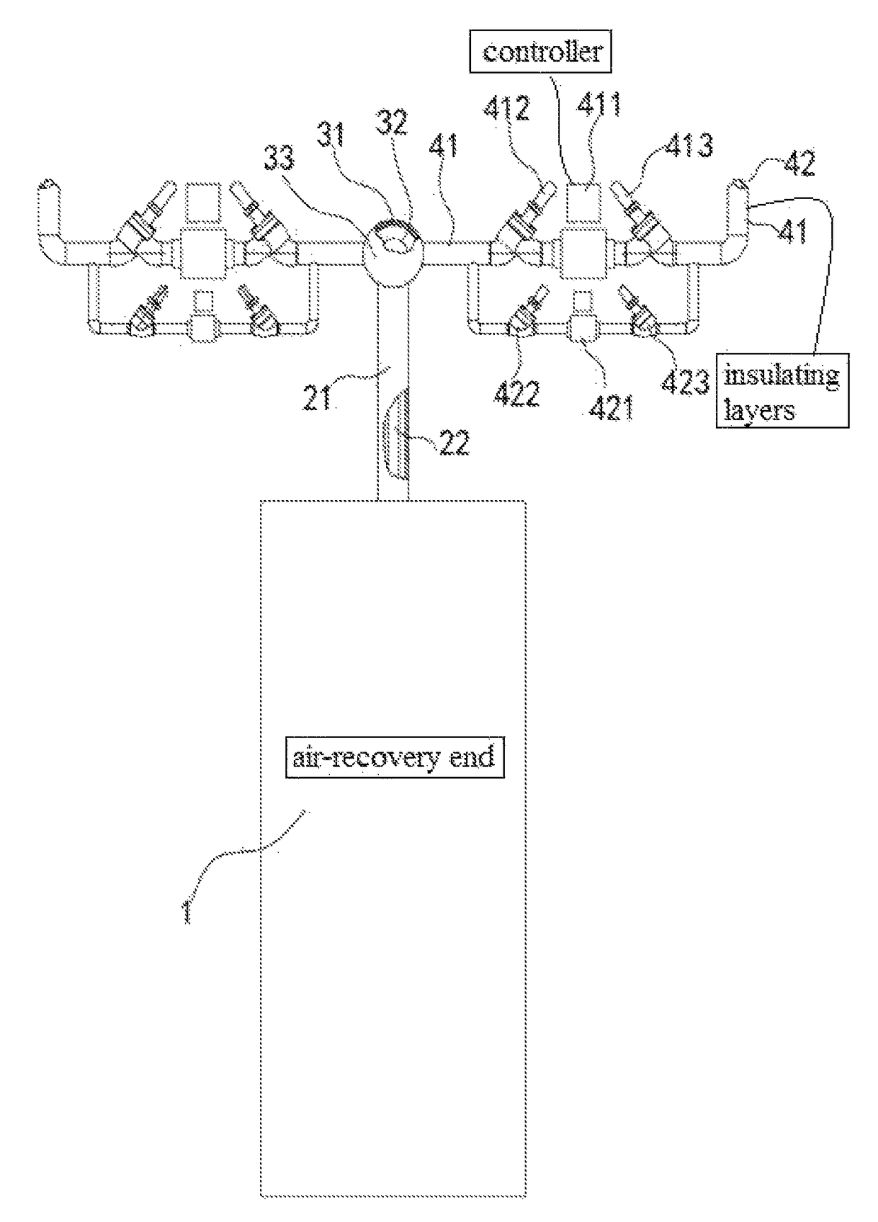
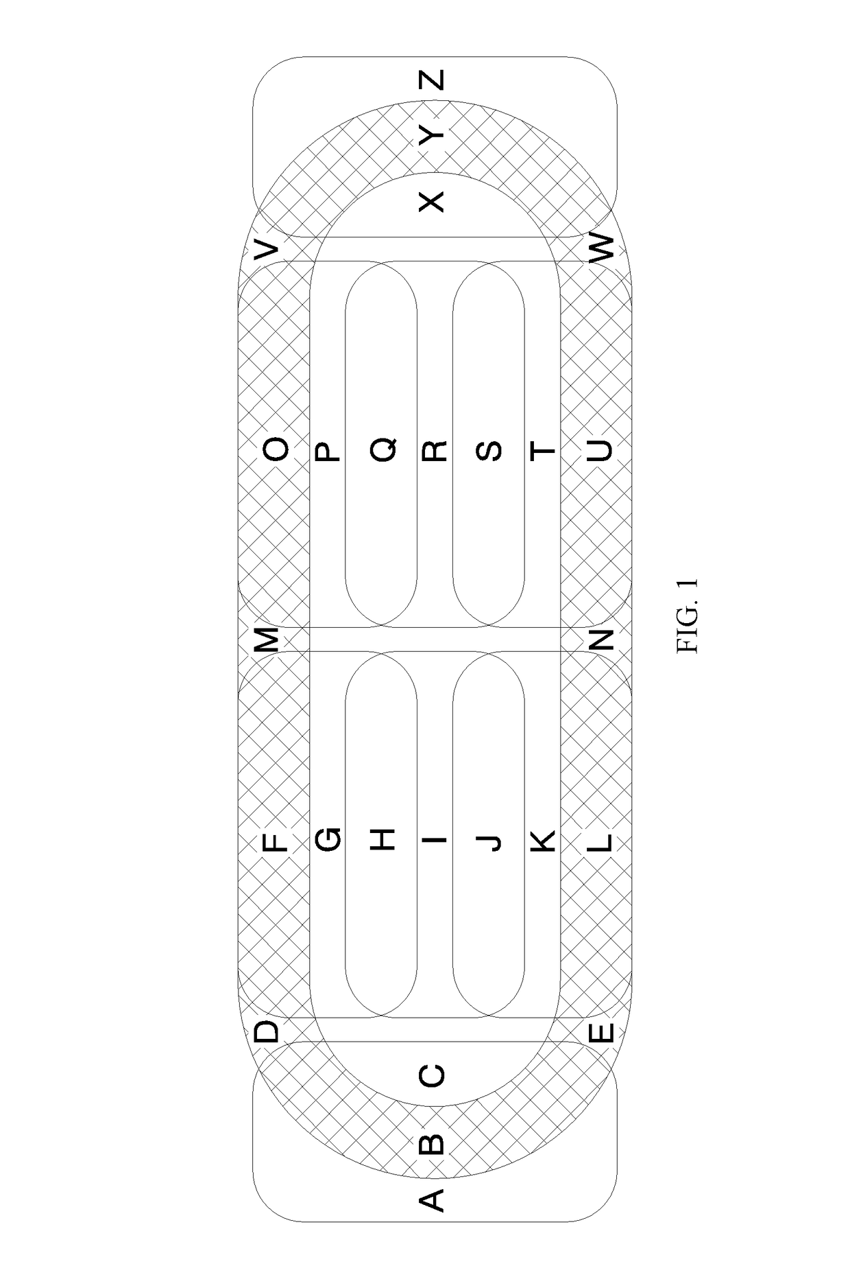
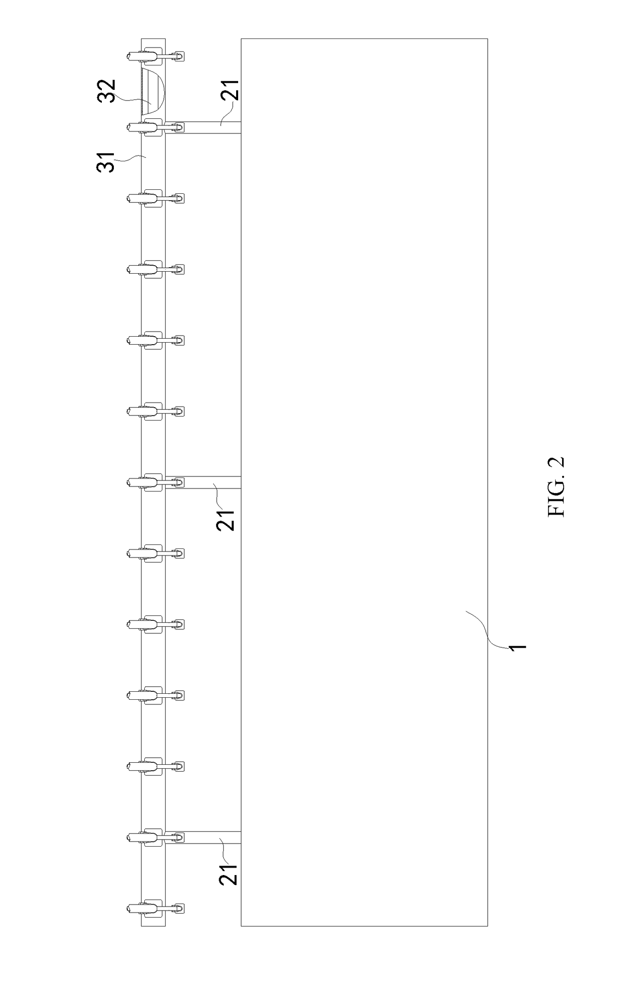
[0023]Referring to the FIG. 1 to FIG. 4, a modular assembled artificial skating rink includes main ice-making devices mounted in an ice-making machine room under an ice surface of the skating rink, and further includes a refrigerating system 1, a plurality of liquid-supply main pipes 42 and air-return main pipes 41 whose number is as the same as the liquid-supply main pipe 42. Each liquid-supply main pipe 42 is sheathed in a corresponding air-return main pipe 41, forming a plurality of groups of sleeve main pipes. The liquid-supply main pipes 42 communicate with a liquid-supply header pipe 32. The air-return main pipes 41 communicate with an air-return header pipe 31. The liquid-supply header pipe 32 is sheathed in the air-return header pipe 31. The air-return header pipe 31 extends along the same length direction as the liquid-supply header pipe 32. Both ends of the air-return header pipe 31 and the liquid-supply header pipe 32 are sealed with sealing plates 33. The refrigerating s...


PUM


Abstract

A modular assembled artificial skating rink includes a refrigerating system, a plurality of liquid-supply main pipes and air-return main pipes in the same pipe line as the liquid-supply main pipes. The liquid-supply main pipes communicate with a liquid-supply header pipe. The air-return main pipes communicate with an air-return header pipe. The liquid-supply header pipe communicates with a refrigerant-fluid outlet of the refrigerating system through at least a liquid-supply standpipe. The air-return header pipe communicates with an air-recovery end of the refrigerating system through at least an air-return standpipe. Each liquid-supply main pipe is sheathed in a corresponding air-return main pipe, forming a plurality of groups of sleeve main pipes. The artificial skating rink is divided into different modular regions. Each of the regions has sleeve manifolds and ice-making pipes. Each liquid-supply main pipe has a refrigerant-fluid control valve bank, and each air-return main pipe has an air control valve bank.

Description

TECHNICAL FIELD[0001]The present invention refers to an artificial ice-making technique, and specifically, refers to a modular assembled artificial skating rink.BACKGROUND[0002]Ice sports are popular with people, and have been developed into varieties of competitive events. Conventional ice sports are held on an ice surface formed naturally under a cold weather condition, which limits the sports to be held only in a region with cold weather. As technology developed, ice sports and ice activities can be held in varieties of regions by an artificial ice-making technique.[0003]A conventional skating rink is a one-piece ice surface on whole grounds made by an artificial ice-making device. For instance, a patent document filed on Nov. 15, 2010, whose application number is 201020608275.0, discloses an assembled-header ice making device for making an artificial skating rink. An ice-making unit is configured for making a refrigerant fluid with a lower temperature. The refrigerant fluid is t...

Claims


Application Information

Patent Timeline
Patent Type & Authority Patents(United States)
IPC IPC(8): F28D7/06E01H4/02F28F1/00E01C13/10A63C19/10F25C3/02
CPCE01C13/105A63C19/10F25C3/02
Inventor LI, GUANG JING
Owner LI GUANG JING
Learn More