
Construction machine

a construction machine and bellows technology, applied in the direction of machines/engines, mechanical equipment, transportation and packaging, etc., can solve the problems of increasing the size of the exhaust gas purifying device including the exhaust pipe as a whole, and the bellows pipe needs a certain length to sufficiently absorb vibration, so as to achieve the effect of absorbing the bellows pipe more efficiently, reducing the number of positions, and increasing the degree of freedom in selecting the length

Active Publication Date: 2017-10-03
NIHON KENKI CO LTD
View PDF13 Cites 0 Cited by
  • Summary
  • Abstract
  • Description
  • Claims
  • Application Information

AI Technical Summary

Benefits of technology

[0007]The present invention is made in view of a problem of the aforementioned conventional art, and an object of the present invention is to provide a construction machine in which the exhaust pipe with the bellows pipe can be arranged efficiently in a limited space around the engine.
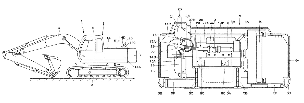
[0010]With this arrangement, the inlet port of the first exhaust gas purifying device is provided on the side opposite to the engine by sandwiching the axis of the cylindrical body of the first exhaust gas purifying device, and the exhaust pipe is extended in the left and right direction of the vehicle body on the front side of the first exhaust gas purifying device. Thus, even if the first exhaust gas purifying device is arranged at a position close to the engine above the hydraulic pump, a length dimension (path) of the exhaust pipe connecting the engine and the first exhaust gas purifying device can be made longer. As a result, the bellows pipe having a length that the relative displacement (vibration) between the engine and the first exhaust gas purifying device can be stably absorbed can be provided on this exhaust pipe.
[0011]The exhaust pipe is disposed in a state extended in the left and right direction of the vehicle body on the front side of the first exhaust gas purifying device. Therefore, there is no need to dispose the exhaust pipe on an upper side of the engine, and a space between the upper side of the engine and an engine cover covering an upper part thereof can be made smaller. As a result, a height dimension of the engine cover can be suppressed, and visibility of a rear of an operator is improved.
[0013]With this arrangement, the inlet port of the first exhaust gas purifying device and the exhaust port of the engine are provided at different positions in the up and down direction, and the bellows pipe is provided on the inclined pipe line part of the exhaust pipe. Therefore, the bellows pipe can cause the relative displacement between the engine and the first exhaust gas purifying device to act on a bending direction of the bellows pipe more easily. As a result, the relative displacement between the engine and the first exhaust gas purifying device can be effectively absorbed by bending deformation of the bellows pipe, and stability of the construction machine can be improved.
[0015]With this arrangement, the first exhaust gas purifying device and the second exhaust gas purifying device are overlapped in the up and down direction in the state connected by the connecting pipe. As a result, the two exhaust gas purifying devices can be arranged in a narrow space around the engine in a compact manner.
[0017]With this arrangement, the first exhaust gas purifying device is located on the upper side of the second exhaust gas purifying device. Accordingly, the exhaust pipe connecting the engine and the first exhaust gas purifying device can be formed longer between the engine and the first exhaust gas purifying device. Therefore, a degree of freedom in selecting a length, a number, a position and the like of the bellow pipe to be provided on the exhaust pipe can be increased. As a result, the relative displacement between the engine and the first exhaust gas purifying device can be absorbed by the bellows pipe more efficiently.

Problems solved by technology

However, the bellows pipe needs some length to sufficiently absorb vibration.
As a result, there is a problem that a size of the exhaust gas purifying device including the exhaust pipe increases as a whole.

Method used


Image

  • Construction machine
  • Construction machine
  • Construction machine

Examples


Embodiment Construction

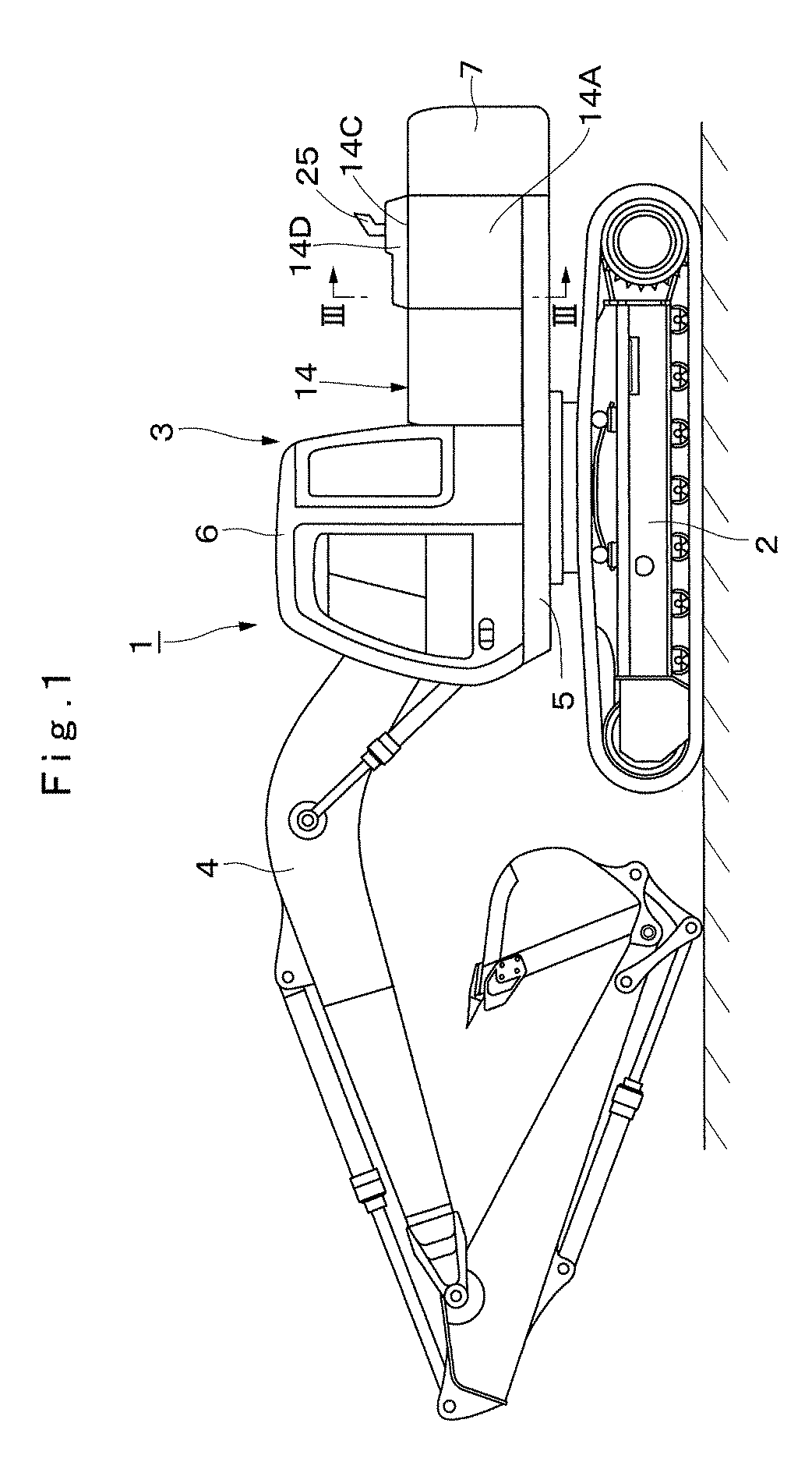
[0029]Hereinafter, as a typical example of a construction machine according to an embodiment of the present invention, a hydraulic excavator on which an engine is mounted will be described as an example in detail by referring to the attached drawings.

[0030]In FIG. 1, designated at 1 is a crawler type hydraulic excavator as a construction machine. This hydraulic excavator 1 is constituted by an automotive crawler type lower traveling structure 2, an upper revolving structure 3 rotatably mounted on the lower traveling structure 2 and constituting a vehicle body together with the lower traveling structure 2, and a working mechanism 4 provided on a front side of the upper revolving structure 3 in a front and rear direction capable of moving upward / downward and performing an excavating work of earth and sand.

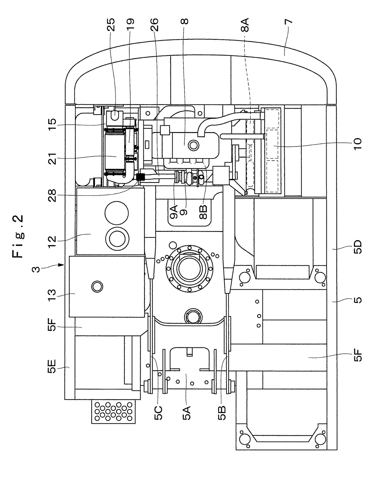
[0031]A revolving frame 5 forms a support structural body of the upper revolving structure 3. As shown in FIGS. 2 and 3, this revolving frame 5 includes a bottom plate 5A made of a t...


PUM


Abstract

An inlet port (17A) of a first exhaust gas purifying device (16) is provided on a side opposite to an engine (8) by sandwiching an axis (O1-O1) of a cylindrical body (17) of the first exhaust gas purifying device (16). An exhaust pipe (26) connecting the engine (8) and the first exhaust gas purifying device (16) is constituted by a lateral pipe line (27) extending in a left and right direction of an upper revolving structure (3) on a front side of the first exhaust gas purifying device (16) and having a bellows pipe (28) in the middle for absorbing relative displacement between the engine (8) and the first exhaust gas purifying device (16) and a bent pipe line (29) bent having a U-shape rearward from a tip end side of the lateral pipe line (27) and connected to the inlet port (17A) of the first exhaust gas purifying device (16).

Description

TECHNICAL FIELD[0001]The present invention relates to a construction machine such as a hydraulic excavator that is provided with an exhaust gas purifying device in an exhaust pipe of an engine, for example.BACKGROUND ART[0002]In general, a hydraulic excavator as a construction machine is constituted by an automotive lower traveling structure, an upper revolving structure mounted rotatably on the lower traveling structure, and a working mechanism provided on a front side of the upper revolving structure, capable of moving upward / downward. On the upper revolving structure, a cab, a fuel tank, an operation oil tank and the like are mounted on the front side of a revolving frame, and an engine, a hydraulic pump and the like are mounted on a rear side of the revolving frame.[0003]For the engine of the hydraulic excavator, a diesel engine is used in general. This diesel engine is said to emit harmful substances such as particulate matters (PM), nitrogen oxides (NOx) and the like. Thus, th...

Claims


Application Information

Patent Timeline
Patent Type & Authority Patents(United States)
IPC IPC(8): B60K13/04F01N3/20F01N13/18E02F9/08F01N13/00
CPCF01N3/208B60K13/04E02F9/0866F01N13/009F01N13/0093F01N13/011F01N13/1805F01N13/1816B60Y2200/412F01N2590/08Y02T10/24Y02T10/12Y02A50/20
Inventor AZUMA, HIROYUKIYAMABAYASHI, JUNKOBAYASHI, TAKAHIRO
Owner NIHON KENKI CO LTD
Learn More