Lock-up device for torque converter

a torque converter and locking device technology, applied in the direction of springs/dampers, rotating vibration suppression, gearing, etc., can solve the problem of axial space required for the installation of the hysteresis torque generating mechanism, and achieve the effect of reducing the weight of the entire torque converter, reducing the space occupied by the dynamic damper device, and effectively inhibiting the variation of rotational speed

Active Publication Date: 2017-10-10
EXEDY CORP
View PDF60 Cites 7 Cited by
  • Summary
  • Abstract
  • Description
  • Claims
  • Application Information

AI Technical Summary

Benefits of technology

[0012]It is an object of the present invention to effectively attenuate variation in rotational speed over wide rotational speed ranges with a compact construction without increasing the number of components.Solution to Problems
[0029]According to the present invention as described above, the lock-up device for a torque converter can effectively attenuate variation in rotational speed over wide rotational speed ranges with a compact construction without increasing the number of components.

Problems solved by technology

Additionally, an axial space is required for installation of the hysteresis torque generating mechanism.

Method used


Image

  • Lock-up device for torque converter
  • Lock-up device for torque converter
  • Lock-up device for torque converter

Examples


Embodiment Construction

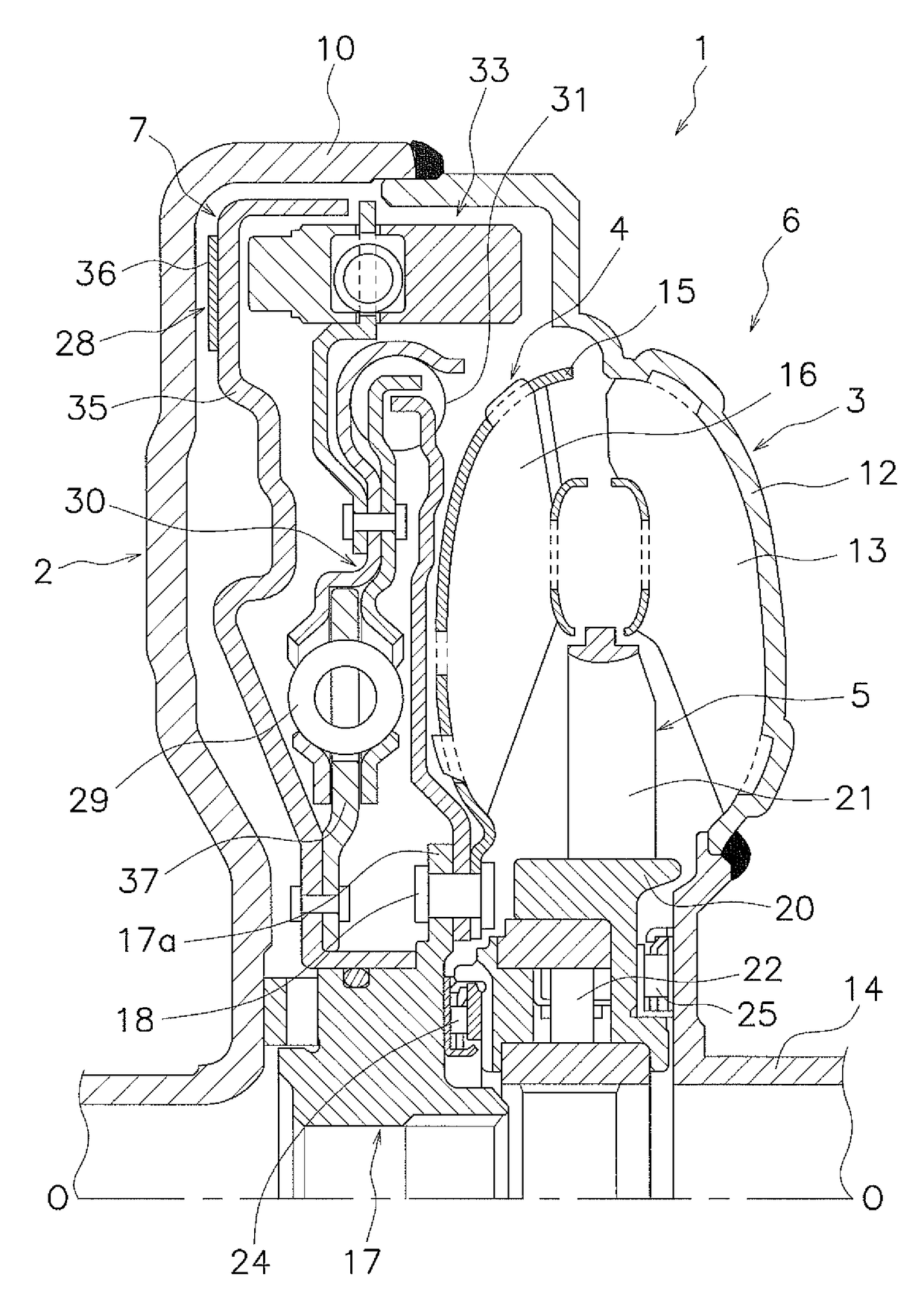
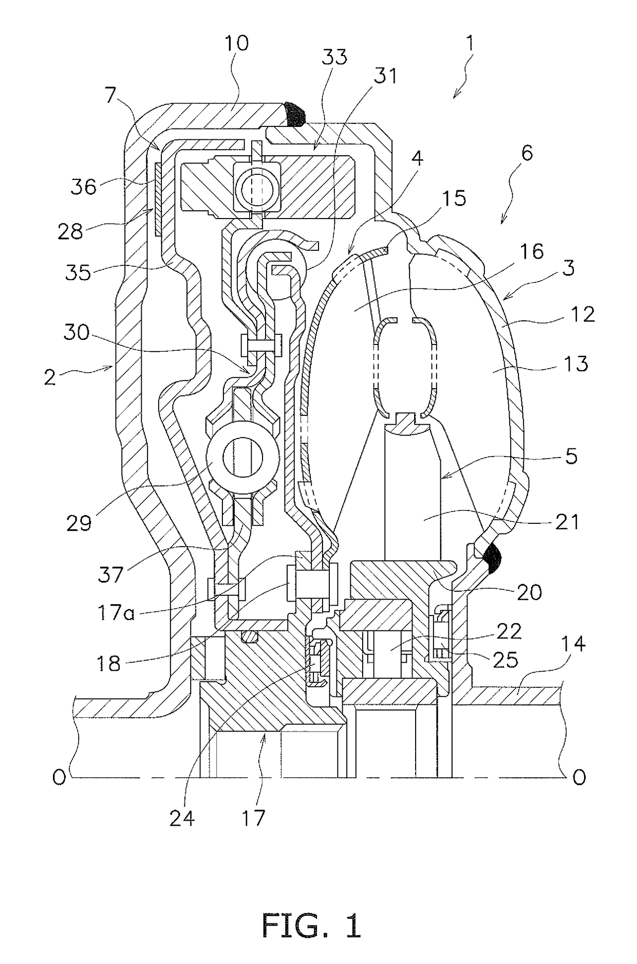
[0037]FIG. 1 is a partial cross-sectional view of a torque converter 1 equipped with a lock-up device according to a first exemplary embodiment of the present invention. In FIG. 1, an engine (not shown in the drawing) is disposed on the left side, whereas a transmission (not shown in the drawing) is disposed on the right side. It should be noted that a line O-O depicted in FIG. 1 indicates a rotational axis of the torque converter and the lock-up device.

[Entire Construction of Torque Converter]

[0038]The torque converter 1 is a device for transmitting a torque from an engine-side crankshaft (not shown in the drawings) to an input, shaft of the transmission, and includes a front cover 2 fixed to an input-side member, a torque converter body 6 composed of three types of vane wheels (an impeller 3, a turbine 4 and a stator 5) and a lock-up device 7.

[0039]The front cover 2 is a disc-shaped member, and an outer peripheral, tubular part 10 is formed on the outer peripheral part of the fron...


PUM


Abstract

A lock-up device for a torque converter is disposed between a front cover coupled to an engine-side member and a torque converter body and directly transmits a torque from the front cover to a turbine of the torque converter. The lock-up device includes a clutch portion to transmit the torque from the front cover to an output side. The lock-up device includes an intermediate member in a power transmission path between the clutch portion and the turbine. An input-side damper mechanism mounted between the clutch portion and the intermediate member attenuates variation in rotational speed. An output-side damper mechanism mounted between the intermediate member and the turbine generates a hysteresis torque larger than a hysteresis torque of the input-side damper mechanism and attenuates variation in rotational speed. The lock-up device also includes a dynamic damper device coupled to the intermediate member and that attenuates variation in rotational speed.

Description

CROSS-REFERENCES TO RELATED APPLICATIONS[0001]This application is the U.S. National Phase of PCT International Application No. PCT / JP2014 / 063076, filed on May 16, 2014. That application claims priority to Japanese Patent Application No. 2013-117889, filed Jun. 4, 2013, and Japanese Patent Application No. 2013-154506, filed Jul. 25, 2013. The contents of all three applications are herein incorporated by reference in their entirety.BACKGROUND[0002]Technical Field[0003]The present invention relates to a lockup device, particularly to a lock-up device for a torque converter, which is disposed between a front cover coupled to an engine-side member and a torque converter body in order to directly transmit a torque from the front cover to a turbine of the torque converter body.[0004]Background Art[0005]A torque converter is embedded with a lock-up device in order to reduce fuel consumption. The lock-up device is disposed between a front cover and a turbine, and is configured to mechanicall...

Claims


Application Information

Patent Timeline
Patent Type & Authority Patents(United States)
IPC IPC(8): F16H45/02F16F15/123F16F15/14
CPCF16H45/02F16F15/12353F16F15/1421F16H2045/0294F16H2045/0226F16H2045/0263F16H2045/0278F16H2045/0205
Inventor TOMIYAMA, NAOKI
Owner EXEDY CORP
Why Eureka
Try Eureka