Supercharge Your Innovation With Domain-Expert AI Agents!

Liquid crystal display device

a liquid crystal display and display device technology, applied in non-linear optics, instruments, optics, etc., can solve the problem of unlikely driving of liquid crystal molecules in the area

Active Publication Date: 2017-10-10
JAPAN DISPLAY INC
View PDF21 Cites 0 Cited by
  • Summary
  • Abstract
  • Description
  • Claims
  • Application Information

AI Technical Summary

Benefits of technology

The patent describes a liquid crystal display device with pixels that include sub-pixels corresponding to different color areas. The device has an electrode with comb tooth portions, and the gap between these portions is different for sub-pixels in different color areas. This results in different slit pitches for sub-pixels of the same type in different color areas, which improves the display's color accuracy and vividness.

Problems solved by technology

This configuration makes the electric field unlikely to be generated in an area on the first electrode, thereby making liquid crystal molecules in the area unlikely to be driven.

Method used


Image

  • Liquid crystal display device
  • Liquid crystal display device
  • Liquid crystal display device

Examples


first embodiment

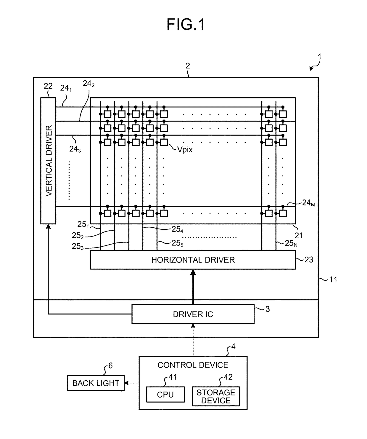
[0041]FIG. 1 is a block diagram of an exemplary system configuration of a liquid crystal display device according to a first embodiment of the present disclosure. A liquid crystal display device 1 is a transmissive liquid crystal display device and includes a display panel 2 and a driver integrated circuit (IC) 3. Flexible printed circuits (FPCs), which are not illustrated, transmit an external signal to the driver IC 3 or driving electric power to drive the driver IC 3. The display panel 2 includes a translucent insulation substrate such as a glass substrate 11, a display area 21, a vertical driver (vertical drive circuit) 22, and a horizontal driver (horizontal drive circuit) 23. The display area 21 is provided on the surface of the glass substrate 11 and has a number of pixels each including a liquid crystal cell and arranged in a matrix (rows and columns). The glass substrate 11 includes a first substrate and a second substrate. The first substrate is provided with a number of p...

second embodiment

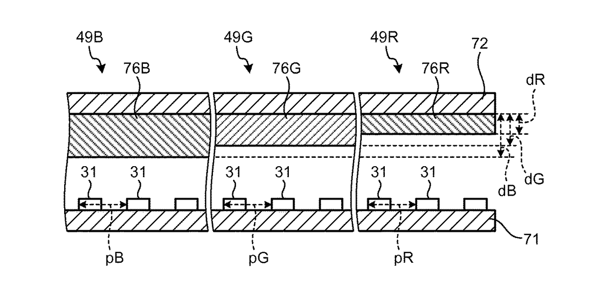
[0127]The liquid crystal display device 1A according to a second embodiment of the present disclosure will be described. FIG. 17 is a block diagram of an exemplary system configuration of the liquid crystal display device according to the second embodiment. FIG. 18 is a schematic view for explaining a pixel array of the liquid crystal display device according to the second embodiment. FIG. 19 is a plan view for explaining a pixel of the liquid crystal display device according to the second embodiment. FIG. 20 is a sectional schematic view for explaining the slit pitch of each sub-pixel in one pixel according to the second embodiment. FIG. 21 is a flowchart of a method for driving the liquid crystal display device according to the second embodiment. Components identical to those described in the first embodiment and the first to the third modifications are denoted by like reference numerals, and overlapping explanation thereof will be omitted.

[0128]FIG. 17 is a block diagram of an ex...


PUM

PropertyMeasurementUnit
total slit length L0aaaaaaaaaa
width w1aaaaaaaaaa

Abstract

According to an aspect, a liquid crystal display device includes: a first substrate; a second substrate; a liquid crystal layer between the first and second substrates; pixels each including sub-pixels corresponding to different color areas; a first electrode in each sub-pixel; and a second electrode facing the first electrode. The first electrode includes an electrode base portion extending in a first direction; and a plurality of comb tooth portions extending in a second direction from the electrode base portion. A slit pitch of a sub-pixel in one color area and a slit pitch of a sub-pixel in the other color area of at least two color areas out of different color areas are different in size, each slit pitch corresponding to a gap between the comb tooth portions adjacent to each other.

Description

CROSS REFERENCES TO RELATED APPLICATIONS[0001]The present application claims priority to Japanese Priority Patent Application JP 2014-134980 filed in the Japan Patent Office on Jun. 30, 2014, and JP 2015-122001 filed in the Japan Patent Office on Jun. 17, 2015, the entire content of which is hereby incorporated by reference.BACKGROUND[0002]1. Technical Field[0003]The present invention relates to a liquid crystal display device provided with liquid crystals and to an electronic apparatus including the liquid crystal display device provided with liquid crystals.[0004]2. Description of the Related Art[0005]There have been developed systems (modes) for driving liquid crystals, including a liquid crystal driving system that uses an electric field generated in a longitudinal direction between substrates, that is, a longitudinal electric field. Examples of a liquid crystal display device that drives liquid crystals using a longitudinal electric field include, but are not limited to, longit...

Claims


Application Information

Patent Timeline
Patent Type & Authority Patents(United States)
IPC IPC(8): G02F1/1343G02F1/1335
CPCG02F1/134363G02F1/133514G02F2001/134345G02F1/134345
Inventor MATSUSHIMA, TOSHIHARUTAKIZAWA, KEIJIUEHARA, TOSHINORI
Owner JAPAN DISPLAY INC
Features
  • R&D
  • Intellectual Property
  • Life Sciences
  • Materials
  • Tech Scout
  • Unparalleled Data Quality
  • Higher Quality Content
  • 60% Fewer Hallucinations
Learn More