Slide lock apparatus for press machine

a technology of slide lock and press machine, which is applied in the direction of mechanical control devices, process and machine control, instruments, etc., can solve the problems of high cost of production, high durability of locking pins and reception holes, and three locking units that require a large space. , to achieve the effect of high reliability, simple construction of locking, and excellent reliability

Active Publication Date: 2017-10-17
PASCAL ENG
View PDF15 Cites 0 Cited by
  • Summary
  • Abstract
  • Description
  • Claims
  • Application Information

AI Technical Summary

Benefits of technology

[0027]According to the present invention, since the locking engagement portions are formed on the pin members, and the first locking member and the first drive means are provided, accordingly it is possible to hold the plurality of pin members in a locked state in their retracted positions. In a similar manner, since the second locking member and the second drive means are provided, accordingly it is possible to hold the plurality of pin members in a locked state in their advanced positions. Due to this, even if the plurality of actuators operate erroneously due to a mistake by the operator or due to a fault of the control system or the like, still the plurality of pin members are not changed over from their advanced positions to their retracted positions due to this erroneous operation, and neither are they changed over from their retracted positions to their advanced positions, so that the reliability of this device is excellent.
[0028]Furthermore since, with this structure, not only are the plurality of pin members locked in their retracted positions with the single first locking member, but also the plurality of pin members are locked in their advanced positions with the single second locking member, accordingly it is possible to simplify the construction for locking the plurality of pin members in their retracted positions and in their advanced positions.
[0029]Moreover, since the plurality of first locking portions of the first locking member engage and release with the locking engagement portions of the plurality of pin members from the circumferential direction, accordingly it is possible to furnish a locking function whose reliability is high. The same also holds for the second locking member.

Problems solved by technology

Moreover, not only do the three locking units require a large space for installation, but the cost of production is high, since each of the locking units is a device that has a complicated construction and includes two oil chambers, two compression springs, a ball locking mechanism that includes a steel ball, and so on.
And since the construction of the safety locking mechanism for a press of Patent Document #2 is such that the locking pins are supported in the reception holes in a cantilevered manner during the locked state, accordingly this is disadvantageous from the viewpoint of ensuring the durability of the locking pins and the reception holes.
Moreover, the locking mechanism is not provided that locks the plurality of locking pins in their retracted positions or in their advanced positions.
Due to this, if the pressure cylinder is erroneously operated due to a mistake by the operator or due to a fault of the control system or the like, then there is a danger that the safety locking mechanism may operate erroneously, so that the shaft member and the slide may be mistakenly changed over from the locked state to the unlocked state; or, conversely, that they may be mistakenly changed over from the unlocked state to the locked state.

Method used


Image

  • Slide lock apparatus for press machine
  • Slide lock apparatus for press machine
  • Slide lock apparatus for press machine

Examples


embodiment 1

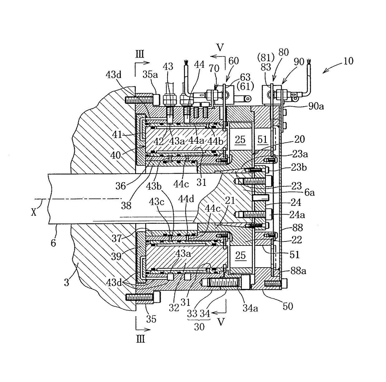
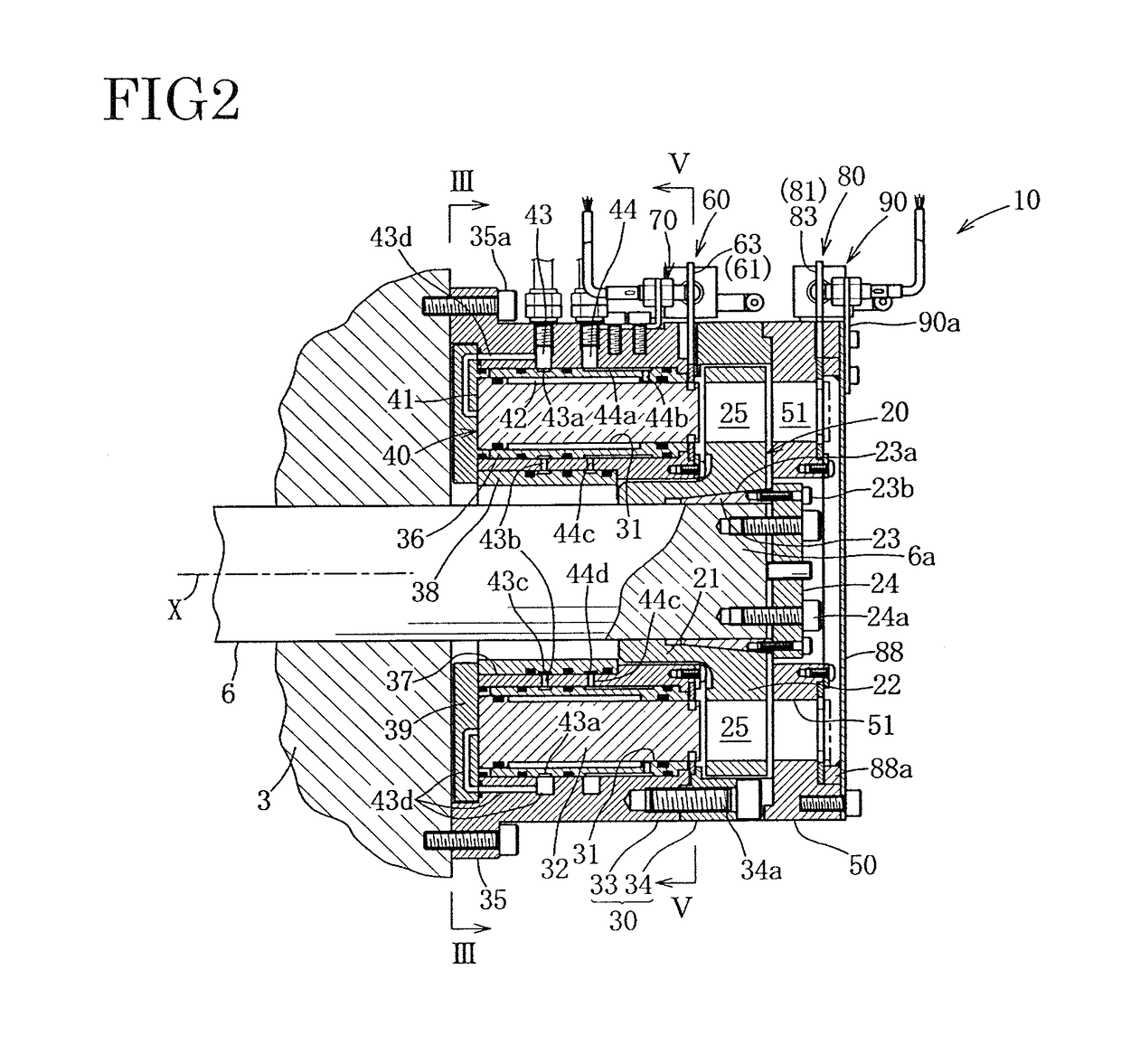
[0047]The slide lock apparatus for a press machine according to the present invention is a device that locks the slide of the press machine by locking a shaft member that rotates together with the raising and lowering operation of the slide, so that the shaft member cannot rotate.

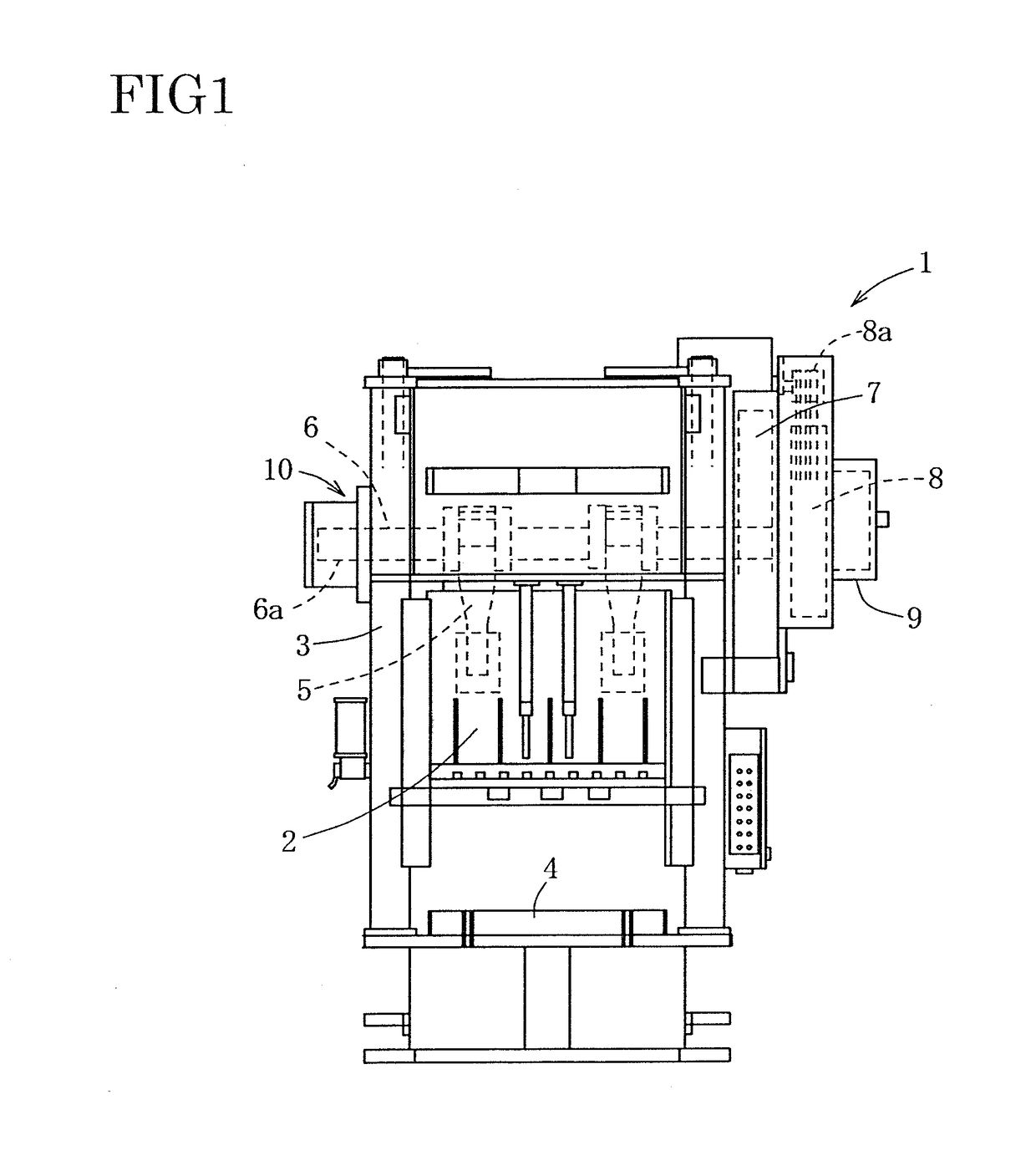
[0048]As shown in FIG. 1, a press machine 1 according to this specific embodiment is a typical crank press, and this press machine 1 comprises a main frame 3, a bolster 4, a slide 2 that is supported on the main frame 3 so as to be freely raised and lowered; a crankshaft 6 (i.e. “shaft member”) that drives the slide 2 up and down via a pair of conrods 5; a main gear 7 that is fixed to the right end portion of the crankshaft 6; a flywheel 8 that is linked to the main gear 7 via gears (not shown); a clutch mechanism 9; an electric motor (not shown) that rotationally drives a pulley 8a which is linked to the flywheel 8; and so on. The slide lock apparatus 10 according to the present invention is attached to an...

embodiment 2

[0097]Next, a slide lock apparatus 10A according to a second specific embodiment will be explained on the basis of FIGS. 11 through 15. However, since this slide lock apparatus 10A is the slide lock apparatus 10 described above, with only the first and second drive means 62, 82 of the first and second locking means 60, 80 and the first and second detection means 70, 90 altered, accordingly only the structures that are different will be explained, while the same reference symbols will be appended to elements that are generally similar and explanation thereof will be omitted.

[0098]As shown in FIGS. 12 and 14, the first drive means 62A of the first locking means 60A comprises a pair of first air cylinders 101 disposed in a pair of cavity portions 100 formed in portions of the annular member 33 between pairs of the reception holes 31, a pair of tension springs 102 that drive the first locking member 61A to return to its locking position, and a pair of circular holes 103 formed in the fi...


PUM


Abstract

A slide lock apparatus for a press machine includes: a flange member fixed over the shaft member for driving the slide, and having a flange portion; an annular main member fixed to the main frame, and having an annular member facing the flange portion; a plurality of reception holes formed in the annular member; a plurality of pin members installed in the plurality of reception holes so as to be shiftable therein; a plurality of actuators for driving the plurality of pin members between retracted positions and advanced positions penetrating into admission holes in the flange portion; a first locking member for locking the plurality of pin members in retracted positions; a first drive device for rotationally driving the first locking member; a second locking member for locking the plurality of pin members in their advanced positions; and a second drive device for rotationally driving the second locking member.

Description

TECHNICAL FIELD[0001]The present invention relates to a slide lock apparatus for a press machine that is capable of stopping the slide of the press machine at a desired stopping position or at a position in the neighborhood thereof.BACKGROUND OF THE INVENTION[0002]Various types of slide lock apparatus have been implemented that lock a slide of a press machine with respect to the main body of the press machine when repairs are to be performed to the machine, repairs are to be performed to a die thereof, or exchange of the die is to be performed, and which prevent the slide from shifting downward.[0003]The slide lock apparatus for a servo press disclosed in Patent Document #1 is a slide lock apparatus that is capable of locking, in any desired position, a large diameter helical gear that drives the slide to go up and down via an eccentric mechanism, by engaging engagement claws with the gear teeth of that gear.[0004]With this slide lock apparatus, three locking units are provided spac...

Claims


Application Information

Patent Timeline
Patent Type & Authority Patents(United States)
IPC IPC(8): G05G5/06B30B15/28
CPCB30B15/28B30B15/287Y10T74/20636
Inventor KITAURA, ICHIROHASHIDATE, AKITAKEKIMURA, SEIJI
Owner PASCAL ENG
Why Eureka
Try Eureka