Supercharge Your Innovation With Domain-Expert AI Agents!

Electro plating device

a technology of electroplating and electrodes, applied in the direction of electroplating, etc., can solve the problem of easy seizure in the joint portion

Active Publication Date: 2017-10-17
VALLOUREC OIL & GAS FRANCE SAS +1
View PDF22 Cites 0 Cited by
  • Summary
  • Abstract
  • Description
  • Claims
  • Application Information

AI Technical Summary

Benefits of technology

This patent describes a way to create a uniform layer of electro plating on a screw in a steel pipe. This helps to prevent any areas from being left unplated.

Problems solved by technology

Since lubricity of the green dope is worse than that of the API dope, the seizure easily occurs in the joint portion.

Method used


Image

  • Electro plating device
  • Electro plating device
  • Electro plating device

Examples


example

[0085]Hereinafter, Examples of the present invention will be described.

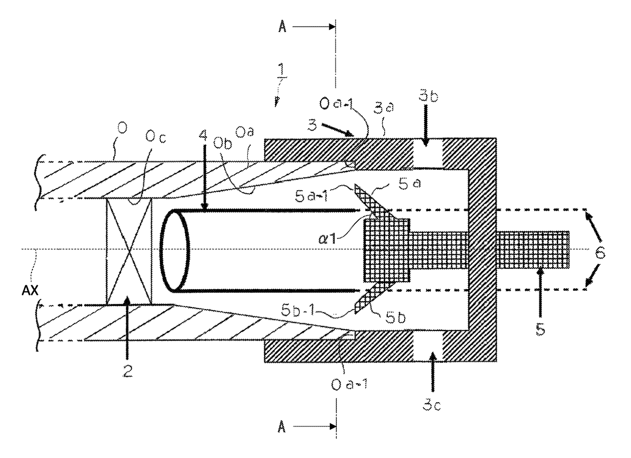
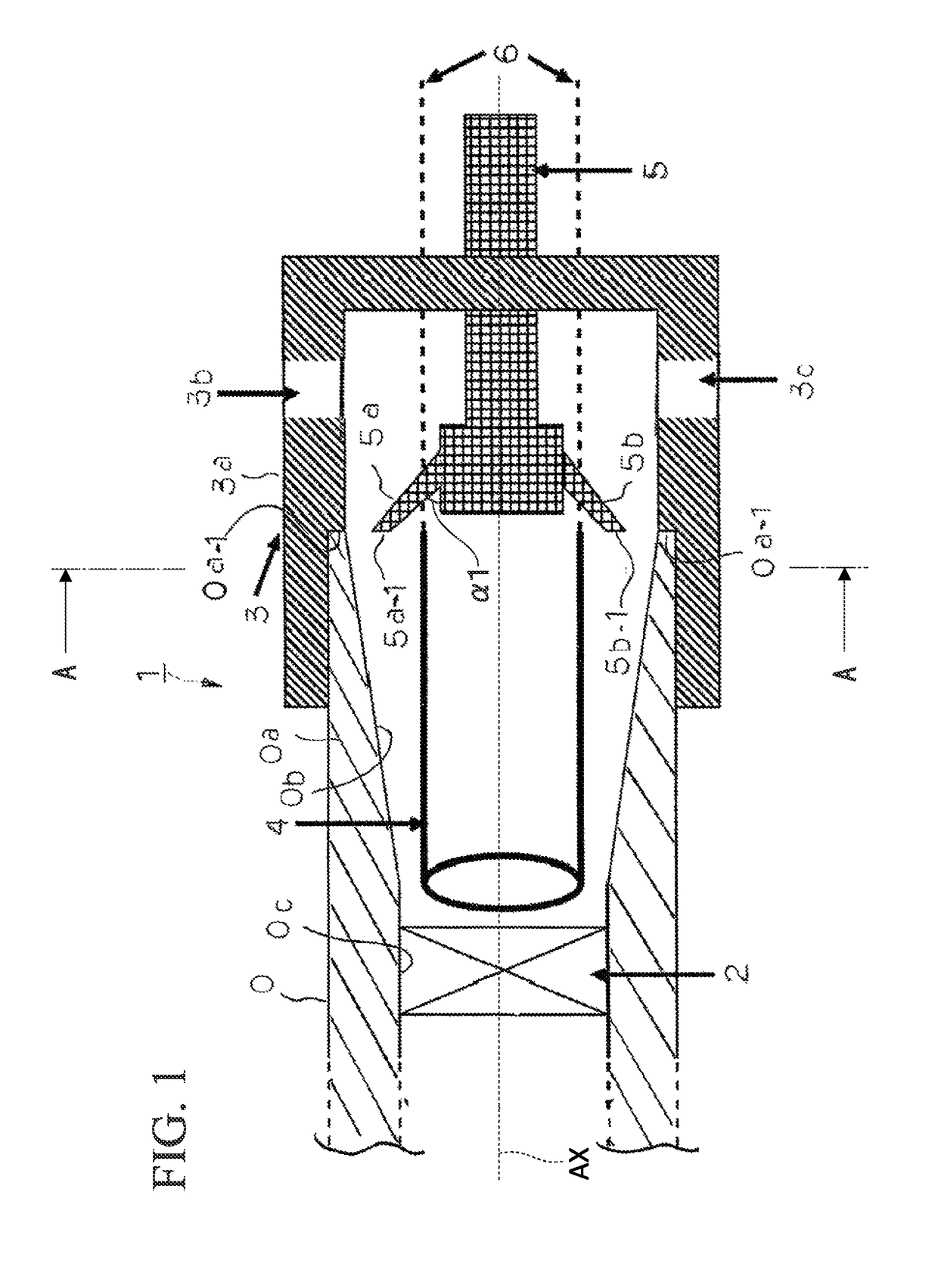
[0086]A degreasing liquid (sodium hydroxide=50 g / L), a Ni-strike bath (nickel chloride=250 g / L and hydrochloric acid=80 g / L), and a copper plating bath (copper sulfate=250 g / L and sulfuric acid=110 g / L) were prepared, and copper plating was performed by processes and conditions shown in Table 1 using the electro plating device 1 shown in FIG. 1.

[0087]

TABLE 1ProcessCathode Electrolytic DegreasingNi-StrikeCopper platingTreatment ConditionBathCurrentTreatmentBathCurrentTreatmentBathCurrentTreatmentTemperatureDensityTimeTemperatureDensityTimeTemperatureDensityTime(° C.)(A / dm2)(second)(° C.)(A / dm2)(second)(° C.)(A / dm2)(second)50660356120508400

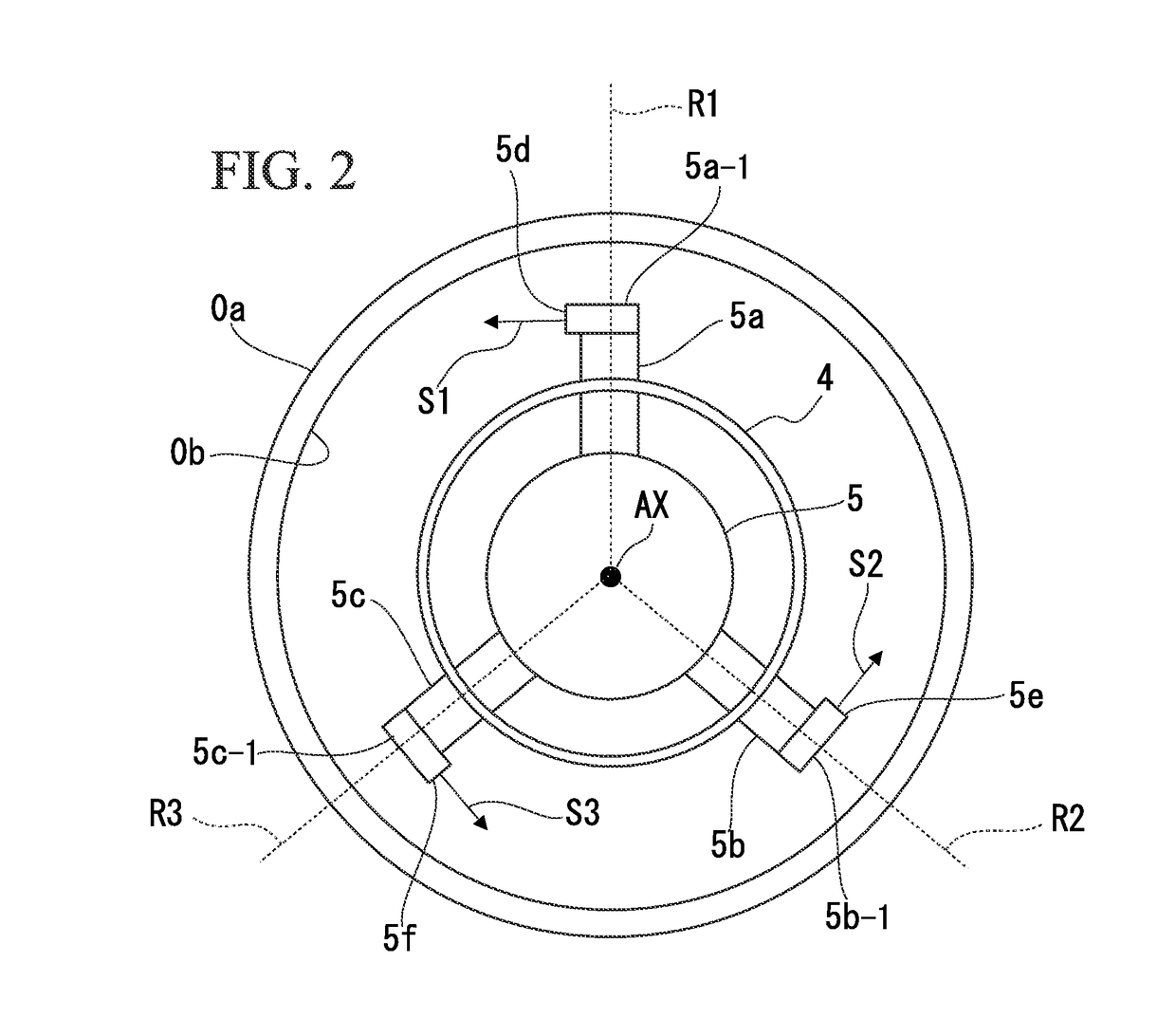
[0088]By changing the plating solution injection nozzle type, the number of the plating solution injection nozzles, and the presence or absence of the atmosphere opening port, the presence or absence of an unplated region (Good: None, Normal: Slight Occurrence, and Bad: Large Occ...


PUM

PropertyMeasurementUnit
intersection angleaaaaaaaaaa
angleaaaaaaaaaa
inclined angleaaaaaaaaaa

Abstract

An electro plating device includes a pipe inside seal mechanism which occludes an inner channel of a steel pipe, a tubular insoluble electrode which is disposed in a pipe end so as to be opposite to a female screw, a plating solution feed mechanism which includes a plurality of nozzles which extend radially with a pipe axis of the steel pipe as a center, and a pipe end seal mechanism which accommodates the nozzles thereinside and is mounted to the pipe end, when viewed in the pipe axial direction, a tip of each of the nozzles is positioned between the female screw and the insoluble electrode, and each of the nozzles injects the plating solution toward a direction which intersects an extension direction of the nozzle, the direction being a rotational direction of a clockwise direction or a counterclockwise direction in which the pipe axis is the center.

Description

TECHNICAL FIELD[0001]The present invention relates to an electro plating device which forms an electro plating layer on a surface of a female screw carved on an inner circumferential surface of a pipe end of a steel pipe.[0002]Priority is claimed on Japanese Patent Application No. 2012-148476, filed on Jul. 2, 2012, and the contents of which are incorporated herein by reference.BACKGROUND ART[0003]In order to collect natural gas or crude oil from underground, a pit is dug toward a natural gas field or an oil field existing at several thousand meters from the ground surface to underground, and it is necessary to install a large transport pipe to the pit. In the transport pipe, a plurality of long steel pipes (so-called oil-well pipes) are connected to each other in a line. In recent years, in the viewpoint of productivity improvement, a need for a screw joint (so-called integral joint) for a steel pipe capable of directly connecting the oil-well pipes without using a coupling is incr...

Claims


Application Information

Patent Timeline
Patent Type & Authority Patents(United States)
IPC IPC(8): C25D7/04C25D17/12C25D5/02C25D5/08
CPCC25D7/04C25D5/02C25D5/022C25D5/08C25D17/12C25D5/627C25D5/611
Inventor KIMOTO, MASANARIISHII, KAZUYAYAMAMOTO, TATSUYA
Owner VALLOUREC OIL & GAS FRANCE SAS
Features
  • R&D
  • Intellectual Property
  • Life Sciences
  • Materials
  • Tech Scout
  • Unparalleled Data Quality
  • Higher Quality Content
  • 60% Fewer Hallucinations
Learn More