
Power reception device and power transmission system

a power reception device and power transmission technology, applied in the direction of generating/distributing signals, liquid/fluent solid measurement, inductance, etc., can solve the problems of difficult to cause the timing at the power transmission side and the timing at the power reception side to conform to each other, and achieve the effect of improving the data detection accuracy

Active Publication Date: 2017-10-17
PANASONIC SEMICON SOLUTIONS CO LTD
View PDF20 Cites 1 Cited by
  • Summary
  • Abstract
  • Description
  • Claims
  • Application Information

AI Technical Summary

Benefits of technology

The present invention aims to improve the accuracy of data detection in a power transmission system where AC power is modulated based on data. This is achieved by synchronizing the power transmission and reception sides, which leads to an improved accuracy of data detection at the power reception side.

Problems solved by technology

Therefore, it is difficult to establish synchronization between the power transmission device and the power reception device, and therefore it is difficult to cause a timing at the power transmission side and a timing at the power reception side to conform to each other in data communication between the power transmission side and the power reception side.

Method used


Image

  • Power reception device and power transmission system
  • Power reception device and power transmission system
  • Power reception device and power transmission system

Examples


embodiment 1

[0045][Schematic Configuration of Power Transmission System]

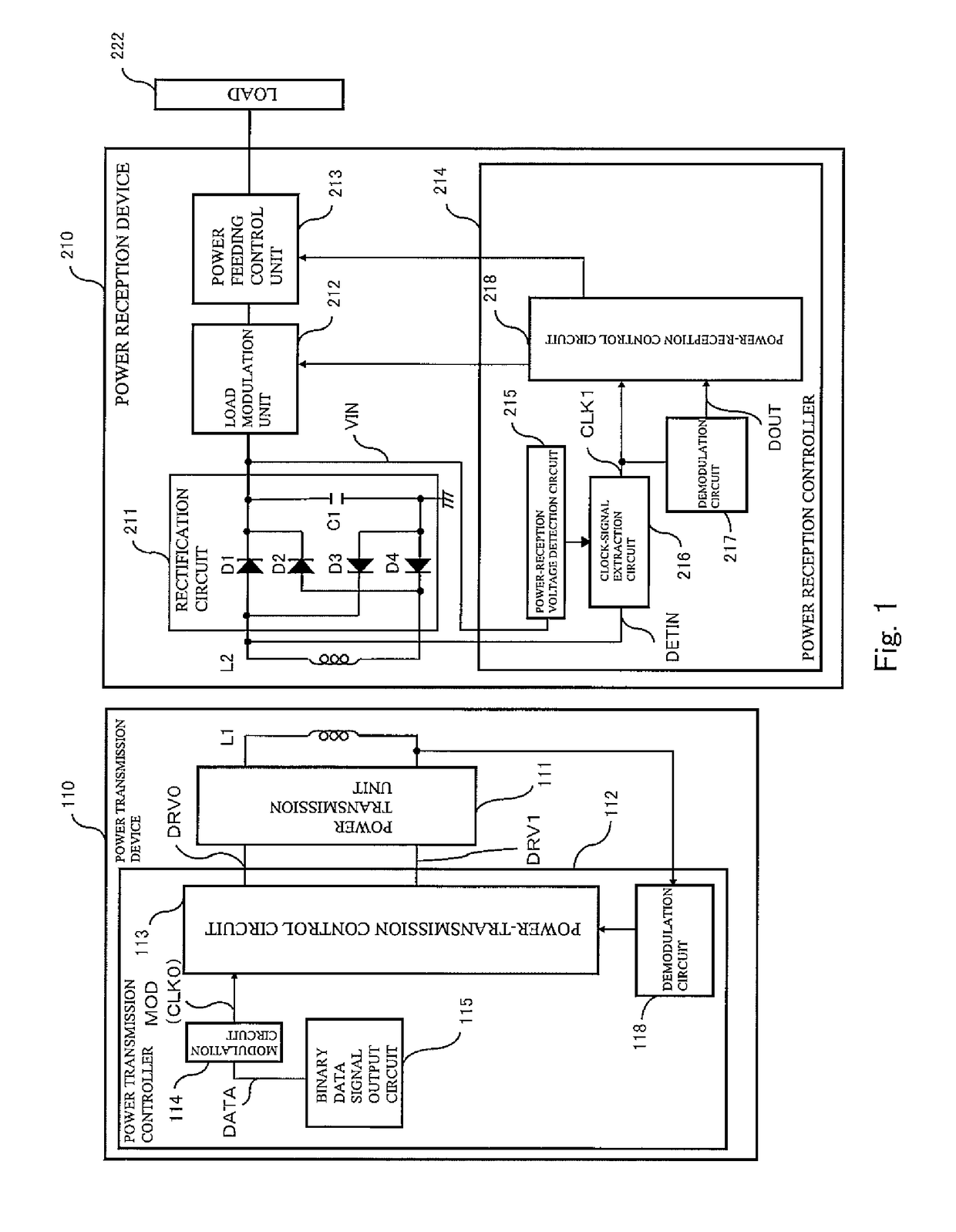
[0046]FIG. 1 is a block diagram showing the configuration of a power transmission system according to Embodiment 1 of the present invention.

[0047]Referring to FIG. 1, the power transmission system includes a power transmission device 110 including a primary coil L1 and a power reception device 210 including a secondary coil L2, and is configured such that the primary coil L1 and the secondary coil L2 are electromagnetically coupled together to construct a power transmission transformer. This enables electric power to be transmitted from the power transmission device 110 to the power reception device 210, and hence the electric power to be supplied to a load 222.

[0048]The power transmission device 110 is built into an apparatus at a power transmission side. The apparatus at the power transmission side is, for example, a charging apparatus. The power reception device 210 is built into electronic equipment at a power reception...

embodiment 2

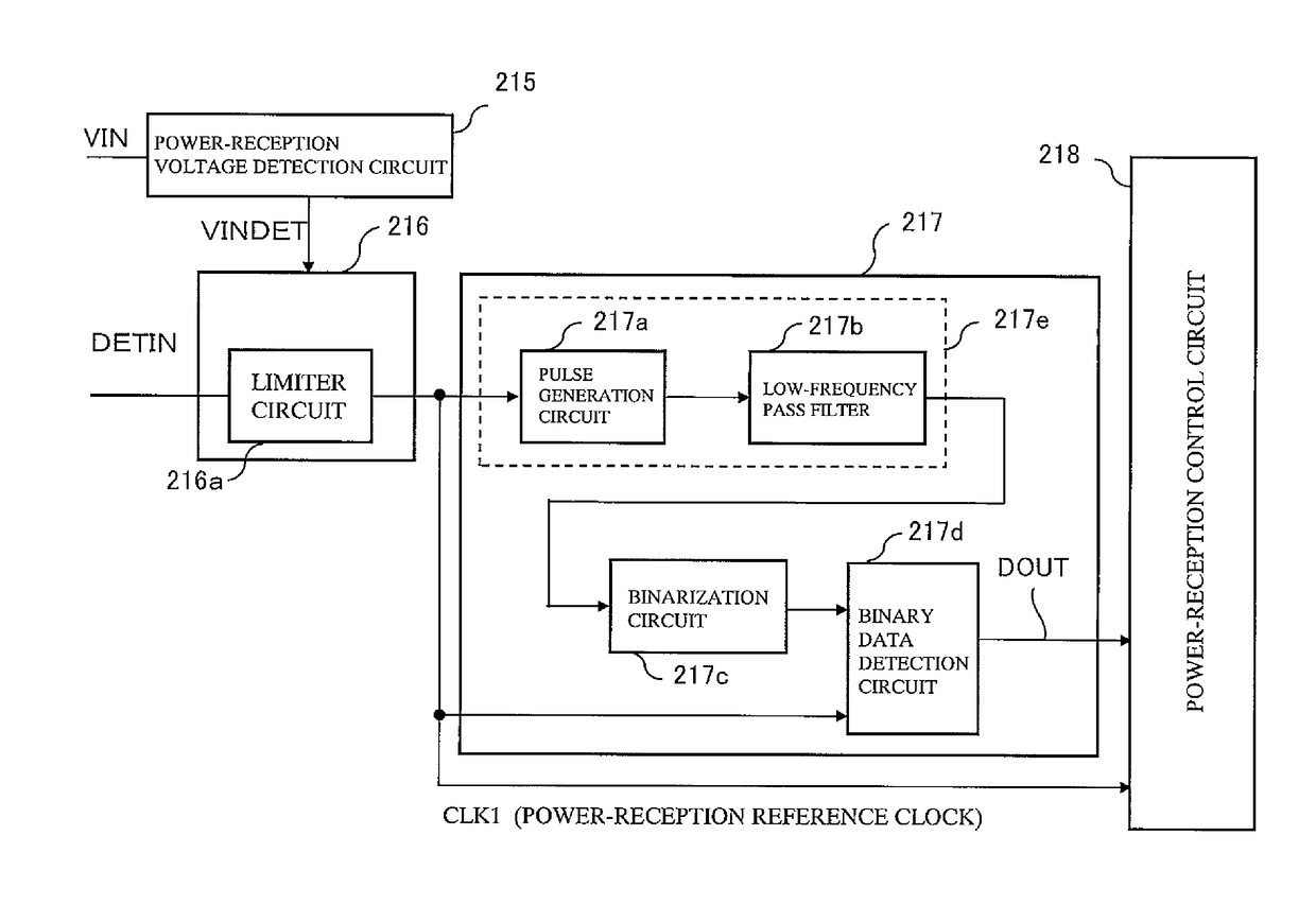
[0093]Hereinafter, Embodiment 2 of the present invention will be described. The power transmission system of Embodiment 2 is identical in configuration to the power transmission system of Embodiment 1 of FIG. 1, except for the demodulation circuit 217. FIG. 11 is a block diagram showing the configuration of the clock-signal extraction circuit 216 and the demodulation circuit 217 in the power transmission system according to Embodiment 2 of the present invention. The demodulation circuit 217 of FIG. 11 is different from the demodulation circuit 217 of FIG. 8 in that the clock signal used in the power-reception control circuit 218 is not the output (clock signal CLK1 at the power reception side) of the clock-signal extraction circuit 216 but is the output (clock signal CLK2) of the pulse generating circuit 217a.

[0094]A power reception device and a power transmission system of the present invention are useful as a power reception device and a power transmission system in which a high ...


PUM


Abstract

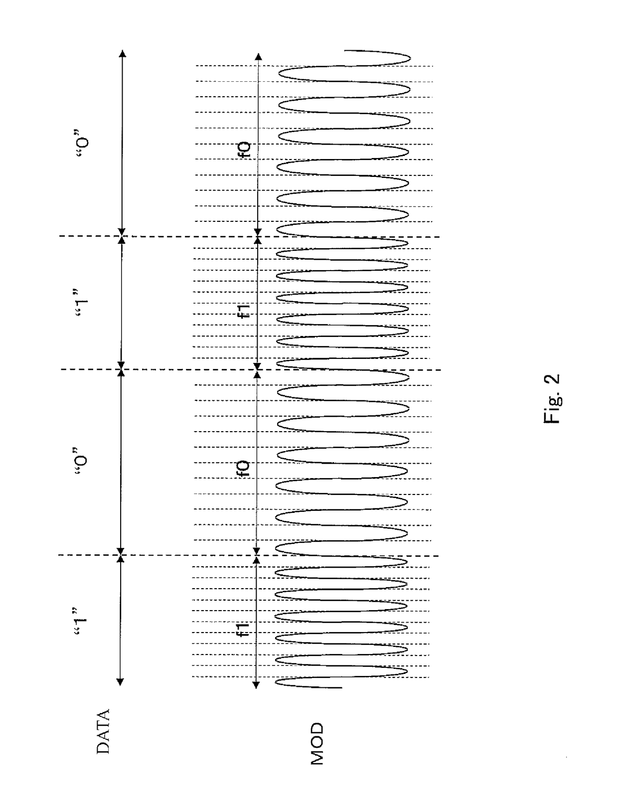
A power reception device in a power transmission system including a power transmission device including a primary coil and the power reception device including a secondary coil, the power transmission device being configured to drive the primary coil and transmit AC power corresponding to a clock signal which is frequency-modulated according to a binary data signal, the primary coil and the secondary coil being electromagnetically coupled together to receive by the secondary coil in the power reception device, the AC power transmitted from the power transmission device, comprises a clock-signal extraction circuit configured to extract the clock signal from an induced voltage induced at one end of the secondary coil in receiving the AC power; and a demodulation circuit configured to generate a pulse synchronously with the clock signal extracted by the clock-signal extraction circuit, and demodulate the pulse to obtain the binary data signal.

Description

CROSS REFERENCE TO RELATED APPLICATIONS[0001]This application is a Continuation of International Application No. PCT / JP2011 / 000787, filed on Feb. 14, 2011, which in turn claims the benefit of Japanese Application No. 2010-074807, filed on Mar. 29, 2010, the disclosures of which Applications are incorporated by reference herein.BACKGROUND OF THE INVENTION[0002]1. Field of the Invention[0003]The present invention relates to a power reception device and a power transmission system.[0004]2. Description of the Related Art[0005]In recent years, a contactless power transmission method (also referred to as wireless power transmission method) which enables power transmission without a contact of a metal portion by utilizing electromagnetic induction has attracted lots of attention. Japanese Laid-Open Patent Application Publication No. 2008-206325 discloses a prior art of such a contactless power transmission method. This prior art discloses that a power transmission device converts clock sig...

Claims


Application Information

Patent Timeline
Patent Type & Authority Patents(United States)
IPC IPC(8): G06F1/12H02J50/10G06F1/26H04B5/00H02J5/00
CPCG06F1/12G06F1/26H02J5/005H04B5/0037H04B5/0093H02J50/80H02J50/10H04B5/266H04B5/79H02J50/12
Inventor OHTA, KAZUYOKIHARA, HIDEYUKINAGATAKE, YOHEIKADA, KYOHEI
Owner PANASONIC SEMICON SOLUTIONS CO LTD
Learn More