
Solar water purifier

Active Publication Date: 2017-10-24
NF IND
View PDF18 Cites 4 Cited by
  • Summary
  • Abstract
  • Description
  • Claims
  • Application Information

AI Technical Summary

Problems solved by technology

In some cases, the energy used may be waste energy from a solar panel.

Method used


Image

  • Solar water purifier
  • Solar water purifier
  • Solar water purifier

Examples


Embodiment Construction

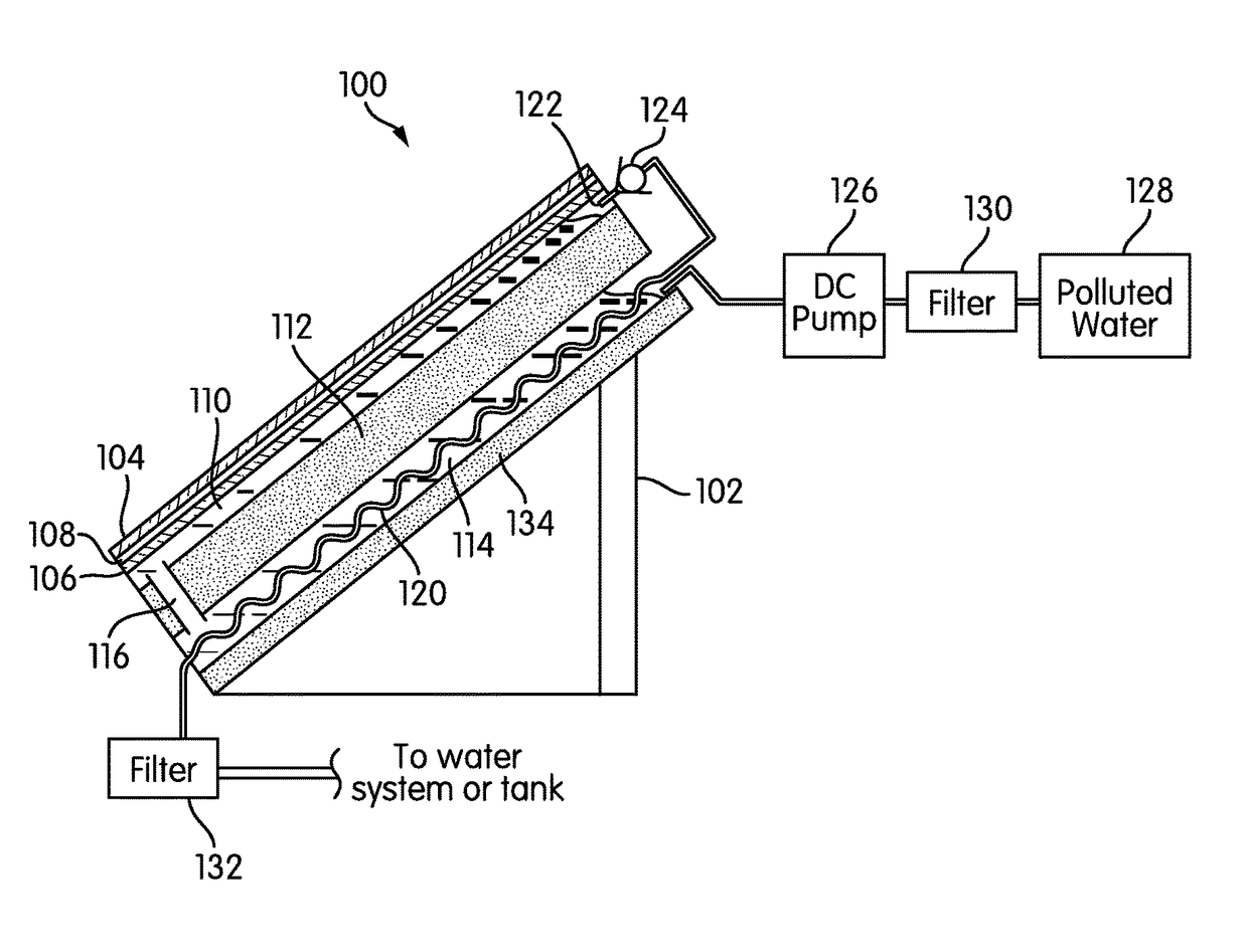
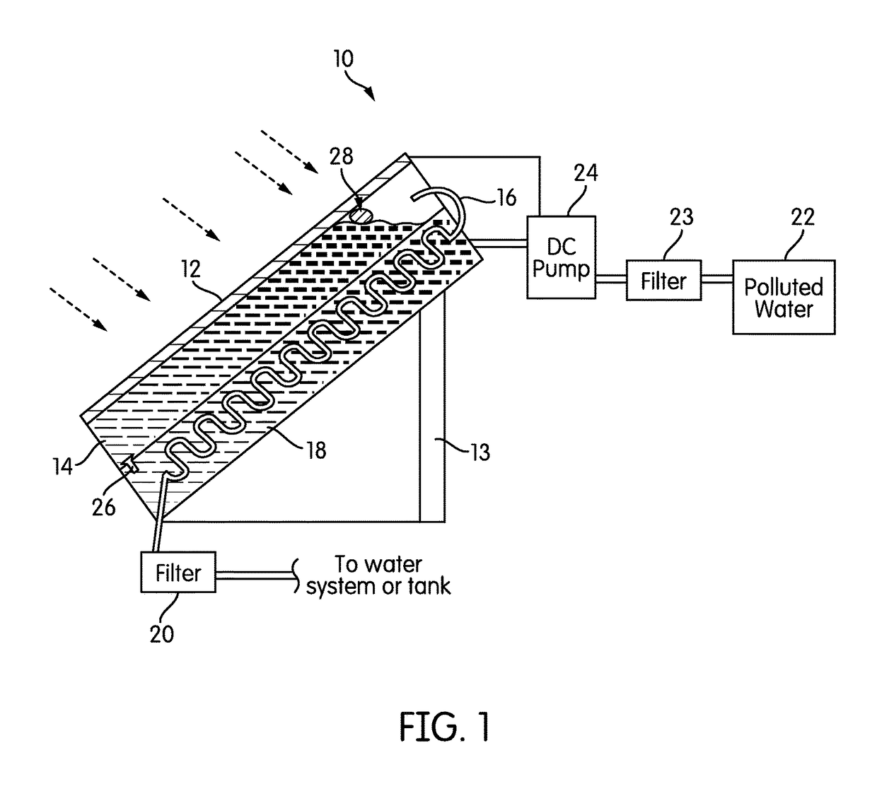
[0017]FIG. 1 is a schematic cross-sectional view of one embodiment of a water purifier, generally indicated at 10. In the water purifier 10, a conventional photovoltaic solar panel 12 is supported on appropriate support structure 13 and is oriented to the sun to absorb its energy. While not shown in FIG. 1, the solar panel 12 may have any type of framing and support elements known in the art.

[0018]As was explained above, in a conventional solar panel, solar energy that cannot be converted to electricity is simply lost, mostly as radiated heat. However, the water purifier 10 makes use of that waste heat and other forms of waste energy to purify water. More specifically, in the water purifier 10, a boiling tank 14 is mounted under the solar panel 12 and in thermal communication with it, such that waste heat is directed into the boiling tank 14. In some embodiments, features may be included to increase or optimize thermal transfer between the solar panel 12 and the boiling tank, includ...


PUM

PropertyMeasurementUnit
depthaaaaaaaaaa
depthaaaaaaaaaa
thicknessaaaaaaaaaa

Abstract

A solar water purifier is disclosed. The solar water purifier uses waste heat from a solar panel, or direct heat from the sun, to boil, evaporate, and condense water to create a stream of purified water. In one embodiment, a boiling tank is mounted under and in direct thermal contact with a solar panel to absorb waste heat. In another embodiment, a transparent wall of the boiling tank is directly exposed to solar energy. Unpurified water enters the boiling tank from an inlet tank. Once in the boiling tank, a stream of steam and water vapor leaves the tank and is allowed to condense within a condenser. The condenser is located within the inlet tank, such that the heat recovered during condensation is used to preheat the inlet water to the boiling tank.

Description

CROSS-REFERENCE TO RELATED APPLICATIONS[0001]This application claims priority to U.S. Provisional Patent Application No. 61 / 832,680, filed Jun. 7, 2013, and also to U.S. Provisional Patent Application No. 61 / 835,185, filed Jun. 14, 2013, the contents of both of which are incorporated by reference herein in their entirety.BACKGROUND OF THE INVENTION[0002]1. Field of the Invention[0003]This invention relates to the use of solar energy to boil and purify drinking water.[0004]2. Description of Related Art[0005]About two billion people do not have access to clean, fresh water. Most of earth's water cannot be used for drinking, cooking, or bathing, due to dissolved natural salts, bacterial or parasitic contamination, or chemical contamination. While unpurified water can often be used for some purposes, it must be purified if it is to be used for drinking Water purification can be done by a number of different processes, including reverse osmosis and evaporation-condensation processes.[000...

Claims


Application Information

Patent Timeline
Patent Type & Authority Patents(United States)
IPC IPC(8): C02F1/14B01D1/00B01D5/00C02F1/00
CPCC02F1/14B01D1/0035B01D5/006B01D5/0015Y02P70/34C02F1/001C02F2201/009C02F2303/04Y02A20/212Y02P70/10
Inventor FAIDI, NAMIRDAVIDOVICH, STEVAN
Owner NF IND
Learn More