
MEMS vaporizer

a technology of electronic mechanical systems and vaporizers, applied in the field of vaporizers, can solve the problems of reducing the reliability of vaporizers, power consumption is relatively high, and the design, commissioning and installation of vaporizers are relatively complicated, so as to achieve the effect of improving reliability, reducing cost and improving precision

Active Publication Date: 2017-10-31
POSIFA TECH LTD
View PDF19 Cites 3 Cited by
  • Summary
  • Abstract
  • Description
  • Claims
  • Application Information

AI Technical Summary

Benefits of technology

The present invention provides several technical effects. Firstly, the vaporizer is made using micro-fabrication techniques, which lowers cost, increases reliability and precision. Secondly, the heater of the vaporizer is placed on a membrane which prevents it from heating the substrate, resulting in higher heating efficiency. Thirdly, the temperature sensor allows for precise measurement of the vaporization temperature, necessary for controlling the heater. Fourthly, the vaporizer can be combined with an air flow sensor, making it useful in electronic cigarettes and other applications such as digital and intelligent systems. Fifthly, the vaporizer is a silicon-based integrated actuator with small size, low power consumption, lower cost, increased reliability and precision, as well as being environmentally friendly.

Problems solved by technology

Several disadvantages can be found with these vaporizers:(1) Due to discrete parts, the design, commissioning and installation of the vaporizer is relatively complicated.(2) Jointing and connecting of the discrete parts significantly reduce the reliability of the vaporizer.(3) Power consumption is relatively high because the heater is not allowed to contact with the vaporized liquid directly.(4) No temperature sensor for measuring the temperature of the heating element directly.(5) Vaporized liquid amount cannot be controlled since no air flow sensor is used for measuring the air flow rate.Therefore, a need exists to overcome the problems with the prior art as discussed above.

Method used


Image

  • MEMS vaporizer
  • MEMS vaporizer
  • MEMS vaporizer

Examples


Embodiment Construction

[0046]The following detailed description of the invention is merely exemplary in nature and is not intended to limit the invention or the application and uses of the invention. Furthermore, there is no intention to be bound by any theory presented in the preceding background of the invention or the following detailed description of the invention.

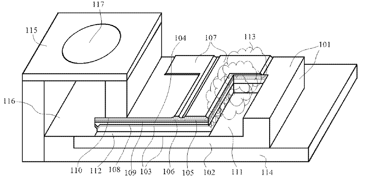
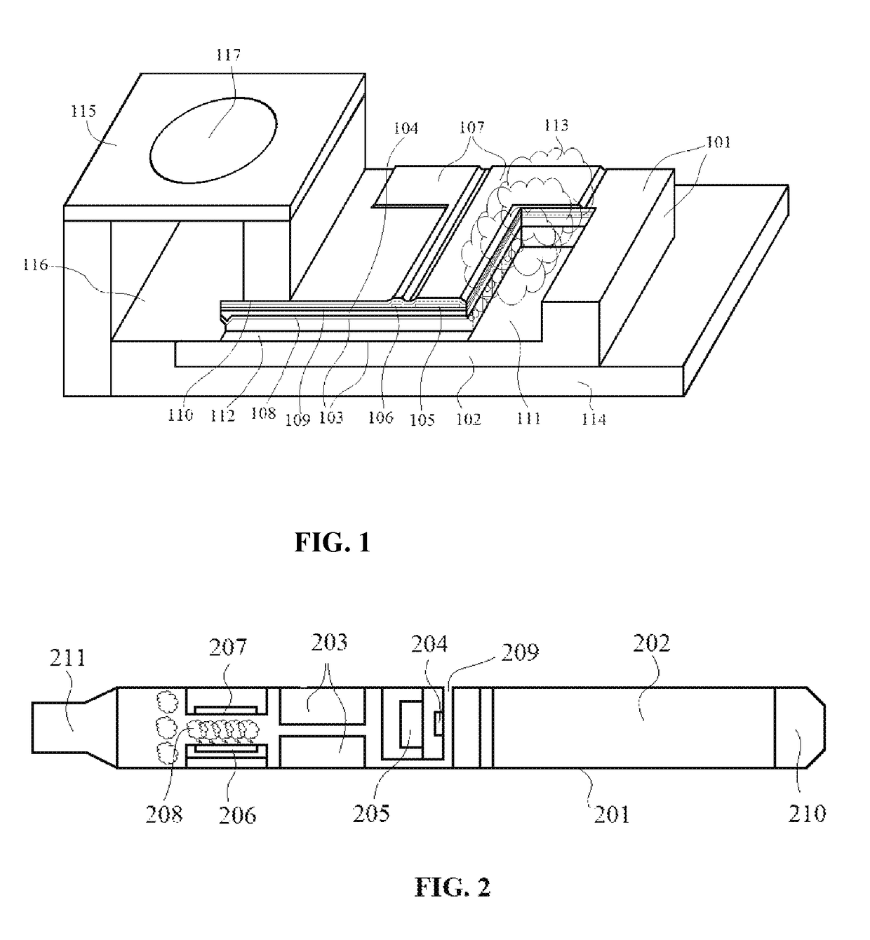
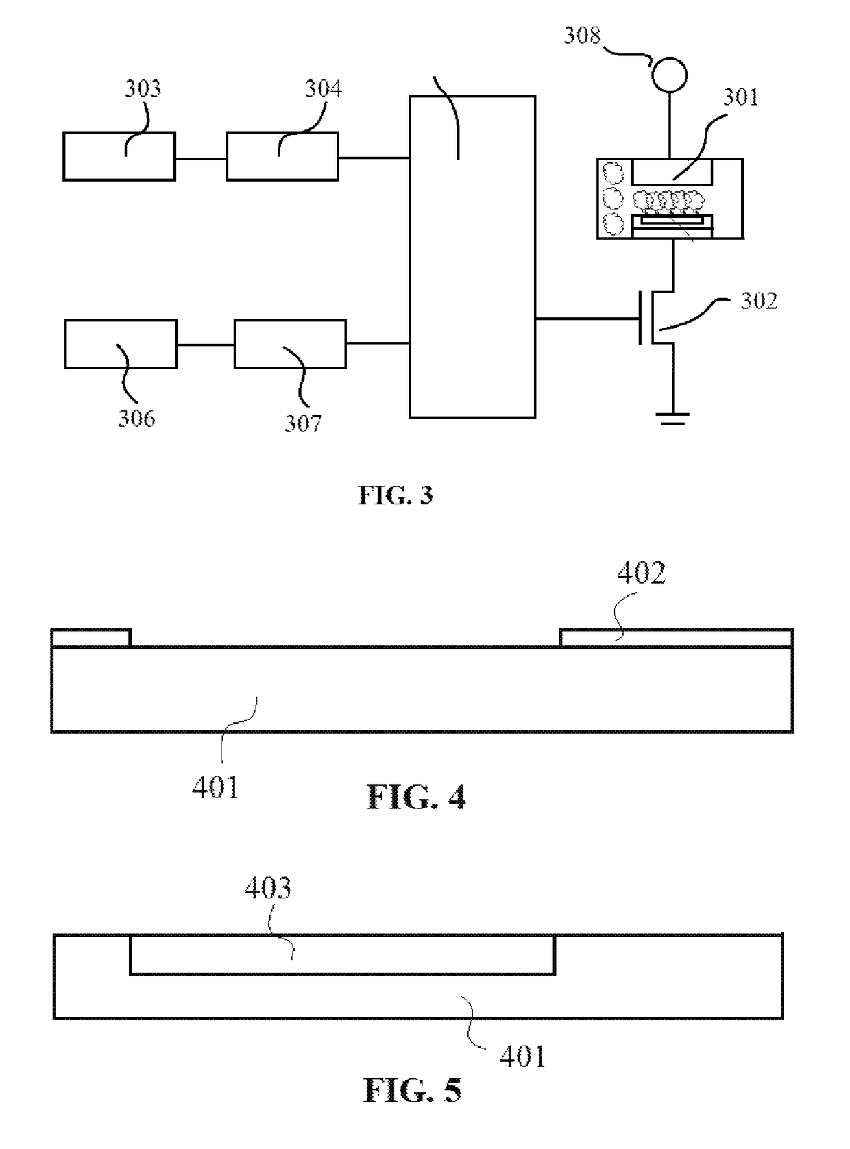
[0047]As shown in FIG. 1, the present invention provides a MEMS vaporizer composing: a silicon substrate 102, a micro-channel array 103 created in the silicon substrate 102, a membrane 104 suspending over the micro-channel array 103 and supported by the silicon substrate 102, a resistance heater 105 disposed on one side portion of the membrane 104 and laterally across one end portion of the top of the micro-channel array 103, a resistance temperature sensor 106 disposed on the membrane 104 and adjacent to the resistance heater 105, two cavities 111 (another not shown in FIG. 1) are recessed in the silicon substrate 102 and connected to the t...


PUM

PropertyMeasurementUnit
widthaaaaaaaaaa
heightaaaaaaaaaa
heightaaaaaaaaaa

Abstract

A MEMS vaporizer is described which can be used for electronic cigarettes. The vaporizer mainly composes: a silicon substrate, a micro-channel array, a membrane suspending over the micro-channel array and supported by the silicon substrate, a resistance heater and a resistance temperature sensor are disposed on the membrane. Since the vaporizer is a silicon-based integrated actuator which provides advantages including small size, compact structure, lower power consumption, lower cost, increased reliability, higher precision, and more environmental friendliness.

Description

FIELD OF THE INVENTION[0001]The present invention relates to a vaporizer used for vaporizing a liquid for a variety of applications. More specifically, the present invention relates to a MEMS (Micro-electro-mechanical-systems) vaporizer and a temperature sensor both integrated in a single silicon substrate which can be used for inhaling the active ingredients of plant material, commonly cannabis, tobacco, or other herbs or blends for the purpose.BACKGROUND OF THE INVENTION[0002]A vaporizer is a device used for vaporizing a liquid for the purpose of inhalation. It is well known that draw-over vaporizers can be used for both civilian and military anesthesia. The earliest vaporizer is an oxford miniature vaporizer which has been in service over 40 years.[0003]Since an electronic cigarette was developed the vaporizer has become popular. The electronic cigarette is a battery-powered vaporizer which simulates tobacco smoking by producing a vapor that resembles smoke. In order to meet the ...

Claims


Application Information

Patent Timeline
Patent Type & Authority Patents(United States)
IPC IPC(8): A24F47/00G03F7/20B23K31/02F22B1/28A24F40/10A24F40/485A24F40/70
CPCA24F47/008F22B1/284F22B1/282A24F40/10A24F40/70A24F40/485
Inventor TU, XIANG ZHENG
Owner POSIFA TECH LTD
Learn More