Thoracic diagnosis assistance system

a technology of thoracic diagnosis and assistance system, applied in the field of thoracic diagnosis assistance system, can solve the problem of not being able to use the thoracic dynamic state image easily, and achieve the effect of easy analysis and diagnosis

Inactive Publication Date: 2017-10-31
KONICA MINOLTA INC
View PDF8 Cites 5 Cited by
  • Summary
  • Abstract
  • Description
  • Claims
  • Application Information

AI Technical Summary

Benefits of technology

[0010]The present invention has been made in consideration of the above problems, and it is one of main objects to provide an image with which a lung field can be easily analyzed and diagnosed.
[0019]According to the present invention, it is possible to provide an image with which a lung field can be easily analyzed and diagnosed.

Problems solved by technology

Therefore, for example, there is a problem that it is not easy to use the thoracic dynamic state image as is for diagnosis by a physician, comparison analysis with image of other individuals, comparison analysis with past images of a same patient, blood flow analysis specifying a position of a blood vessel, etc.

Method used


Image

  • Thoracic diagnosis assistance system
  • Thoracic diagnosis assistance system
  • Thoracic diagnosis assistance system

Examples


first embodiment

[First Embodiment]

[Configuration of Thoracic Diagnosis Assistance System 100]

[0045]First, the configuration is described.

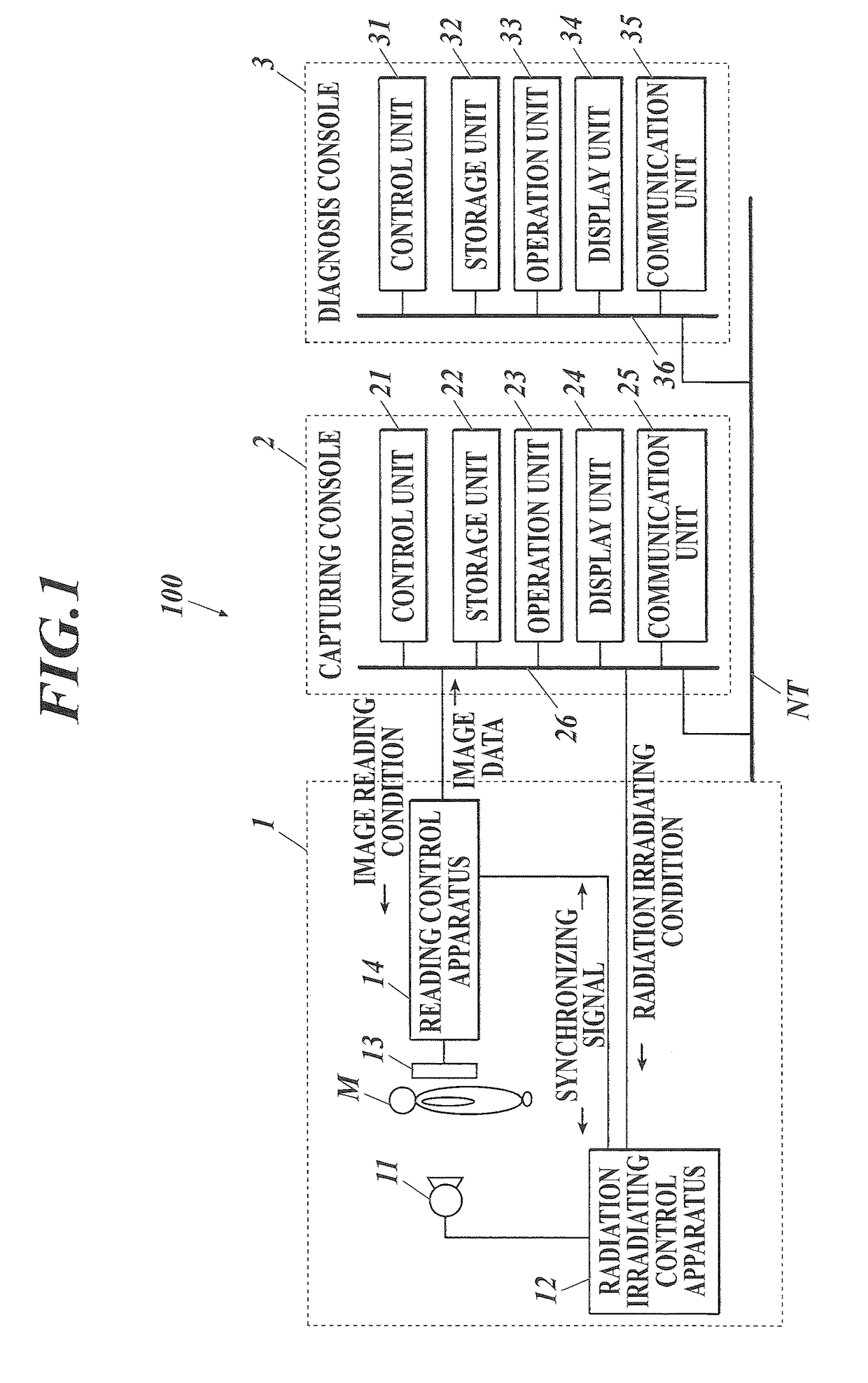
[0046]FIG. 1 shows an entire configuration of a thoracic diagnosis assistance system 100 of the present embodiment.

[0047]As shown in FIG. 1, the thoracic diagnosis assistance system 100 is configured by connecting a capturing apparatus 1 with a capturing console 2 through a communication cable, etc. and connecting a capturing console 2 with a diagnosis console 3 through a communication network NT such as a LAN (Local Area Network), etc. Each apparatus composing the thoracic diagnosis assistance system 100 complies with a DICOM (Digital Image and Communications in Medicine) standard, and communication between the apparatuses are performed according to DICOM.

[Configuration of Capturing Apparatus 1]

[0048]The capturing apparatus 1 is a capturing unit to capture a state of the chest portion moving in cycles, such as change in shape from expansion and contraction of the...

second embodiment

[Second Embodiment]

[0169]Next, the second embodiment of the present invention is described.

[0170]The second embodiment assists diagnosis for each blood vessel in the lung field.

[0171]The configuration of the thoracic diagnosis assistance system 100 and the operation of the capturing console 2 of the second embodiment is similar to those described in the first embodiment, and therefore the description is incorporated herein. According to the second embodiment, the operation of the image analysis processing is different from the first embodiment, and therefore is described below.

[0172]Below, the flow of the image analysis processing (image analysis processing C) is described with reference to FIG. 11. The image analysis processing C is executed by the control unit 31 in coordination with the program stored in the storage unit 32.

[0173]First, the blood vessel template image is used and the blood vessel of the lung field region is labeled in the string of frame images of the dynamic sta...


PUM


Abstract

According to one implementation, the system includes, a capturing unit, a deforming unit, and a generating unit. The capturing unit captures a dynamic state of a thoracic portion to generate a plurality of frame images. The deforming unit sets a reference point in a position corresponding to each other among the plurality of generated frame images. The deforming unit extracts a lung field region from each of the frame images. The deforming unit deforms a shape of the lung field region so that a distance from the set reference point to an outline of an outer side of the lung field region becomes a certain distance. The generating unit analyzes a dynamic state in the lung field region and generates an analysis result image showing a result of the analysis in a corresponding position in the deformed lung field region.

Description

CROSS REFERENCE[0001]The present invention claims priority under 35 U.S.C. §119 to Japanese Application No. 2013-176971 filed Aug. 28, 2013, the entire content of which is incorporated herein by reference.BACKGROUND[0002]Field of the Invention[0003]The present invention relates to a thoracic diagnosis assistance system.[0004]Description of Related Art[0005]Instead of stationary image capturing and diagnosis by thoracic radiation using a conventional film / screen or photostimulable phosphor plate, there is an approach to capture a thoracic dynamic state image using a semiconductor image sensor such as an FPD (flat panel detector), etc., to be applied to diagnosis. Specifically, fast responsiveness of reading and deleting of image data of the semiconductor image sensor is used and pulsed radiation is successively irradiated from a radiation source to match with the timing of reading and deleting by the semiconductor image sensor to perform capturing a plurality of times in one second. ...

Claims


Application Information

Patent Timeline
Patent Type & Authority Patents(United States)
IPC IPC(8): G06K9/00G06T7/11G06T5/00A61B5/113A61B5/026A61B6/00A61B5/00
CPCA61B5/026A61B6/5264G06T5/006G06T7/11A61B5/113G06T2207/30061A61B5/743A61B6/461A61B6/486A61B6/507A61B6/5217A61B6/54A61B6/563G06T2207/10116G06T2207/20101
Inventor NOJI, SHO
Owner KONICA MINOLTA INC
Why Eureka
Try Eureka