
Real-time, limited orientation sensor auto-calibration

a limited orientation and real-time technology, applied in the field of borehole magnetic measurements obtained, can solve problems such as degrading magnetometer data, and achieve the effect of reducing sensor configuration

Active Publication Date: 2017-10-31
BAKER HUGHES INC
View PDF29 Cites 5 Cited by
  • Summary
  • Abstract
  • Description
  • Claims
  • Application Information

AI Technical Summary

Benefits of technology

The present patent provides a method for correcting measurement errors in a down hole tool used for magnetic and accelerometer measurements. The method involves disposing the tool in a borehole with at least three directional sensors, where the sensors are substantially orthogonal to each other and one axis of each set is parallel to the longitudinal axis of the tool. The sensor data is then used to determine the sensor biases and the local tool magnetic field, which can be used to correct the sensor data. The corrected sensor measurements are then used to extract the magnetic anomaly field vector, which is recorded and used for further processing. The method can be applied to a reduced sensor configuration with at least two directional sensors. The technical effect of the patent is to provide a reliable and accurate measurement of magnetic and accelerometer data in down hole tools, even in the presence of residual measurement errors.

Problems solved by technology

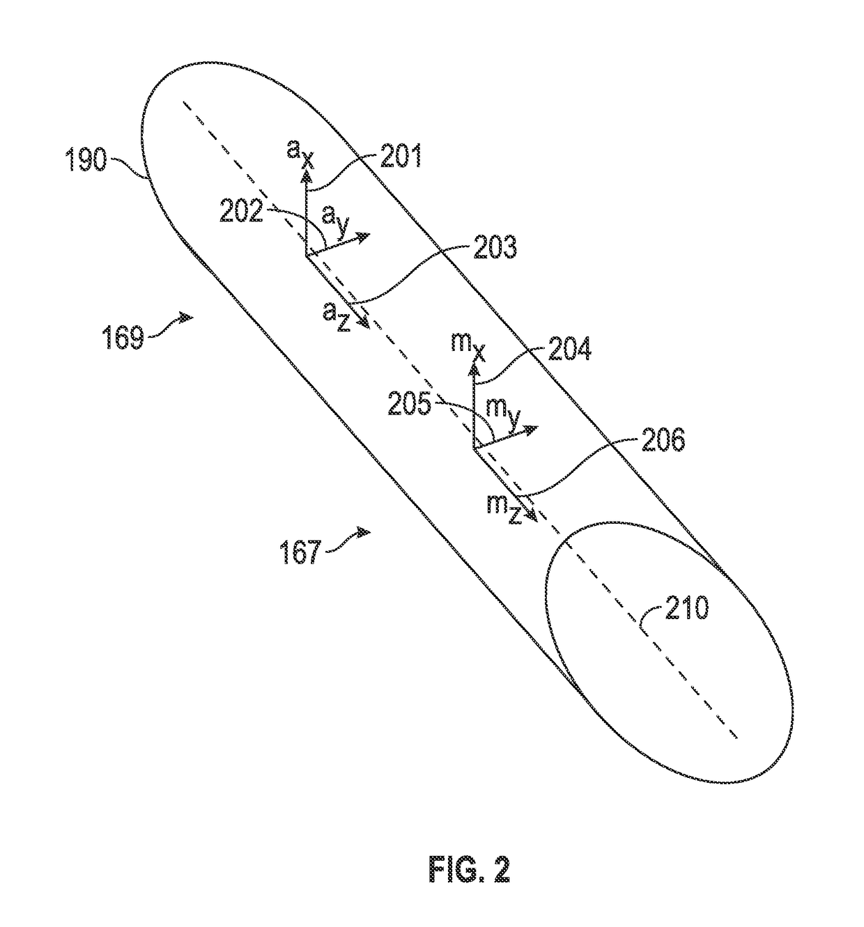
These accelerometers and magnetometers sensors contain measurement errors that are intrinsic to the sensor itself, and in the case of magnetometer may be due magnetic sources within the conveyance system, including sensor housings.
Although accelerometer and magnetometer measurements are useful, and in many cases necessary, for logging operations, each accelerometer and magnetometer includes various measurement errors that affect its measurements.
These errors may be due, for example, to bias (or offset), misalignment, different axial locations and different sensitivities of the accelerometer and magnetometer components.
However, some magnetic anomalies are within the range of sensitivity of the typical magnetometers and if uncorrected generally degrade the magnetometer data.

Method used


Image

  • Real-time, limited orientation sensor auto-calibration
  • Real-time, limited orientation sensor auto-calibration
  • Real-time, limited orientation sensor auto-calibration

Examples


third embodiment

[0032]In the various methods of tool bias correction disclosed herein, the systemic sensor errors, such as a magnetometer bias or an accelerometer bias, may be determined to within a selected accuracy prior to applying the determined bias to correct magnetometer and / or accelerometer measurements. The present disclosure may include reducing the residual measurement error (tool bias) from a first value outside of a selected quality threshold to a second value that is within the selected quality threshold, using any of the methods disclosed herein. For example, in one embodiment, an Extended Kalman Filter may be used to obtain a magnetometer tool bias to within a selected threshold value. In another embodiment, a min-max method may be used to determine minimum and maximum values of magnetometer measurements during a complete revolution of the drill string, thereby allowing a tool bias correction based on minimum and maximum values. In a third embodiment, survey measurements obtained fr...

case 1

[0153 processes the entire data interval and estimates a constant component of the tool string's magnetic field for non-constant tool. This method determines all or most of the tool string magnetization. In Case 1 a largest valid data range is selected and processes over the entire selected interval as a single data set. Case 1 uses only one execution of the basic algorithm.

case 2

[0154 processes very short intervals, 1<t<<L, where L may be the number of data acquisition points over which an anomaly is observed, after the constant field component correction yields the time or spatially dependent magnetic disturbance. The length of the interval is generally greater than one data point, and may be determined by a log analyst and / or interpreter.

[0155]Case 2 selects a processing interval, e.g. 0.1 to 1 ft or longer. Shorter intervals will have higher resolution and higher noise. The interval will be processed according to the basic methods, steps described with respect to Eqs. (101)-(104) and the initial guess for a given interval will be the solution from the previously-determined interval. The intervals may be processed by stepping to an entirely new interval after convergence (or non-convergent exit) or a sliding solution may be developed where the next value is calculated by stepping along the data by one (or more) data points after each solution, producing a...


PUM


Abstract

A system method and computer-readable medium for correcting measurements obtained by a down hole tool for residual measurement errors is disclosed. A down hole tool having at least two directional field sensors is disposed in a borehole. The at least two directional sensors are substantially orthogonal to each other and to a longitudinal axis of the down hole tool. Measurements are obtained from the at least two directional sensors during rotation of the tool by at least 360 degrees around the longitudinal axis of the tool. Residual measurement errors are determined for the obtained measurements, and a quality level of the determined residual measurement errors selected. The determined residual measurement errors are applied to the obtained measurements when the determined residual measurement errors are consistent with the selected quality level. In various embodiments, the residual measurement errors are reduced from a first value that does not match the selected quality level to a second value that are consistent with the selected quality level.

Description

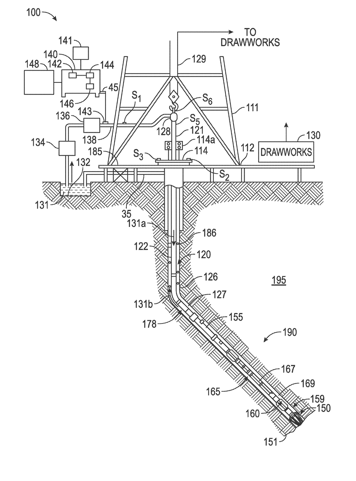
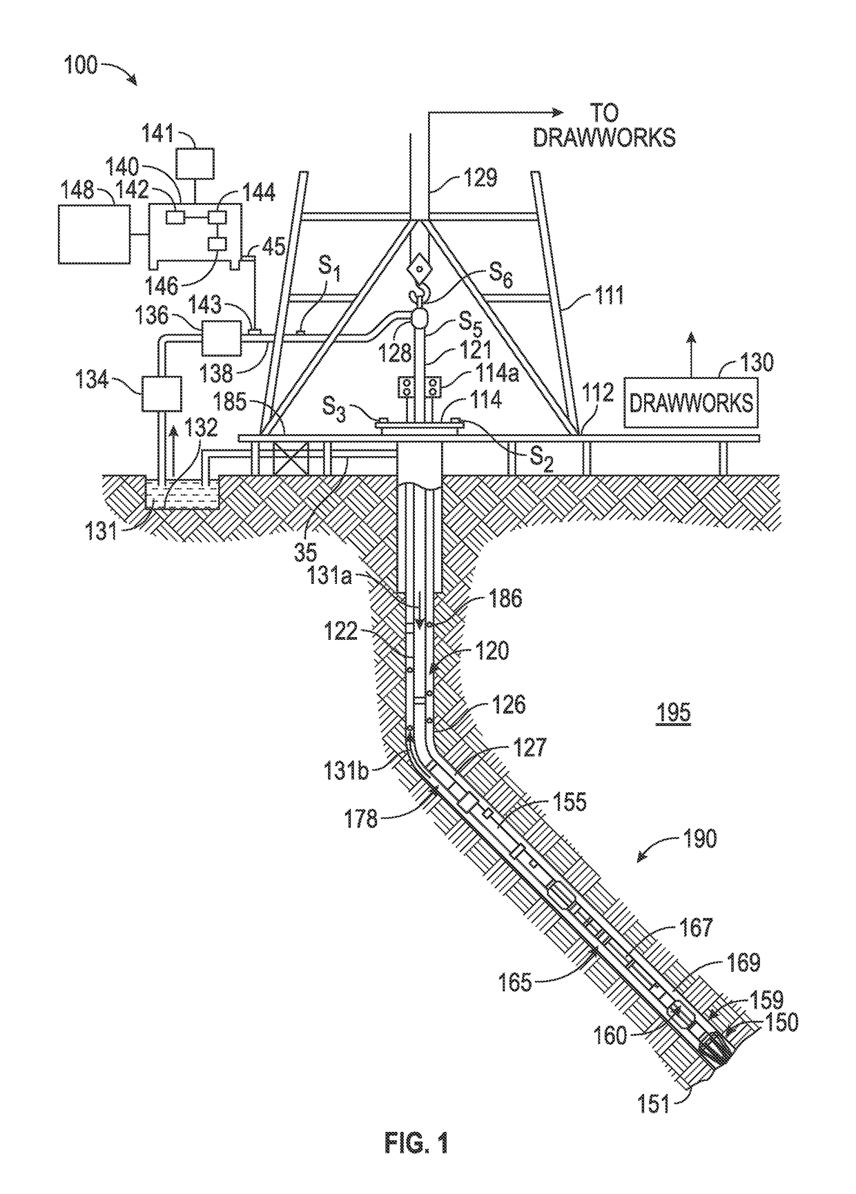
BACKGROUND OF THE DISCLOSURE[0001]1. Field of the Disclosure[0002]The present disclosure is related to magnetic measurements obtained in a borehole and, in particular, to determining a residual measurement error in measurements obtained using a magnetometer or an accelerometer in a borehole.[0003]2. Description of the Related Art[0004]Petroleum exploration generally includes conveying sensors into the well bore for characterizing the down hole formations. The sensor data is used to create various logs recording the properties of the formation. These logs may be obtained either using a measurement-while-drilling process (MWD) a measurement-after-drilling (MAD) process in which sensors are conveyed on the drill string, or using an after drilling process in which sensors are lowered into the wellbore on cable, pipe strings or tubing (these last three are generally described by wireline to differentiate from MWD and MAD). Sensors such as accelerometers and magnetometers are usually incl...

Claims


Application Information

Patent Timeline
Patent Type & Authority Patents(United States)
IPC IPC(8): G01V3/26E21B47/09G01V13/00G01V7/04G01V11/00G01V7/00G01V3/40
CPCG01V3/26E21B47/0905G01V7/005G01V11/00G01V13/00G01V7/04G01V7/00G01V3/40E21B47/092
Inventor ESTES, ROBERT A.RIGGS, RANDY R.HANAK, FRANCIS CHADPRIEST, JOHN F.
Owner BAKER HUGHES INC
Learn More