Tensionally secured screening panel

Active Publication Date: 2017-11-07
NEFF LAWRENCE MILLARD
View PDF24 Cites 3 Cited by
  • Summary
  • Abstract
  • Description
  • Claims
  • Application Information

AI Technical Summary

Benefits of technology

[0013]Accordingly, a need has arisen for a panel that overcomes the shortcomings. Generally, in accordance with the exemplary embodiments, the present invention provides an integrally formed, as defined below, panel comprising a spring for tensioning the annular member to the picket with a locking tab and an anchor lock that releasably latch to tensionally secure

Problems solved by technology

Finally, the applicant explains that the three-sided device of U.S. Pat. No. 5,622,356 may be disengaged from the post upon contact, if the fasteners are not used, and that the adhesive of U.S. Pat. App. Pub. No. 20050005540 adds material cost and may be prone to deterioration that may weaken the respective joint.
Second, apparatuses have multiple interconnecting and interengaging parts.
First, in loosely contacting, the panel may rattle, vibrate, or move resulting in a failure to screen, undesirable noise, and a visually unappealing screen.
Second, adhesives deteriorate and the panels loosen resulting in detachment, noise, and misalignment.
Next, making holes for screws, bolts, rivets, fasteners, connectors, or any or any other similar fasteners or connection leads to corrosion or deterioration of the picket and

Method used


Image

  • Tensionally secured screening panel
  • Tensionally secured screening panel
  • Tensionally secured screening panel

Examples


Example

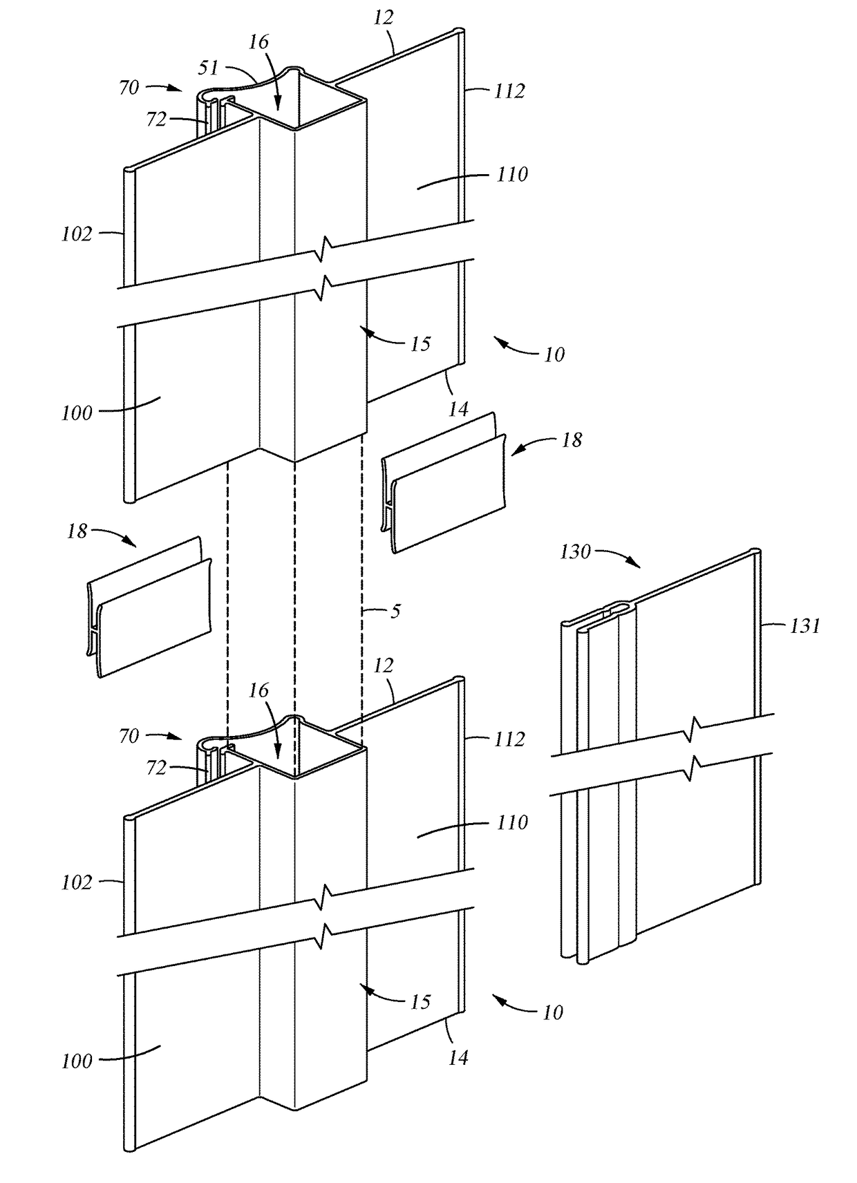
[0046]For purposes of the present description, the term “integrally formed” means that the present invention is made of a continuous, non-segmented, and unitary construction where all elements extend longitudinally and are joined together upon the exit from a mold or tooling, and the present invention is not made by a structural integration such as welding, gluing, bolting, fastening, riveting, screwing or otherwise similarly structurally integrating any elements. The term “integrally formed” does not mean that that the present invention cannot be trimmed, notched, or customized or that the present invention cannot be altered by drilling or punching holes or slots or connected in tandem or in a side-by-side relation for screening.

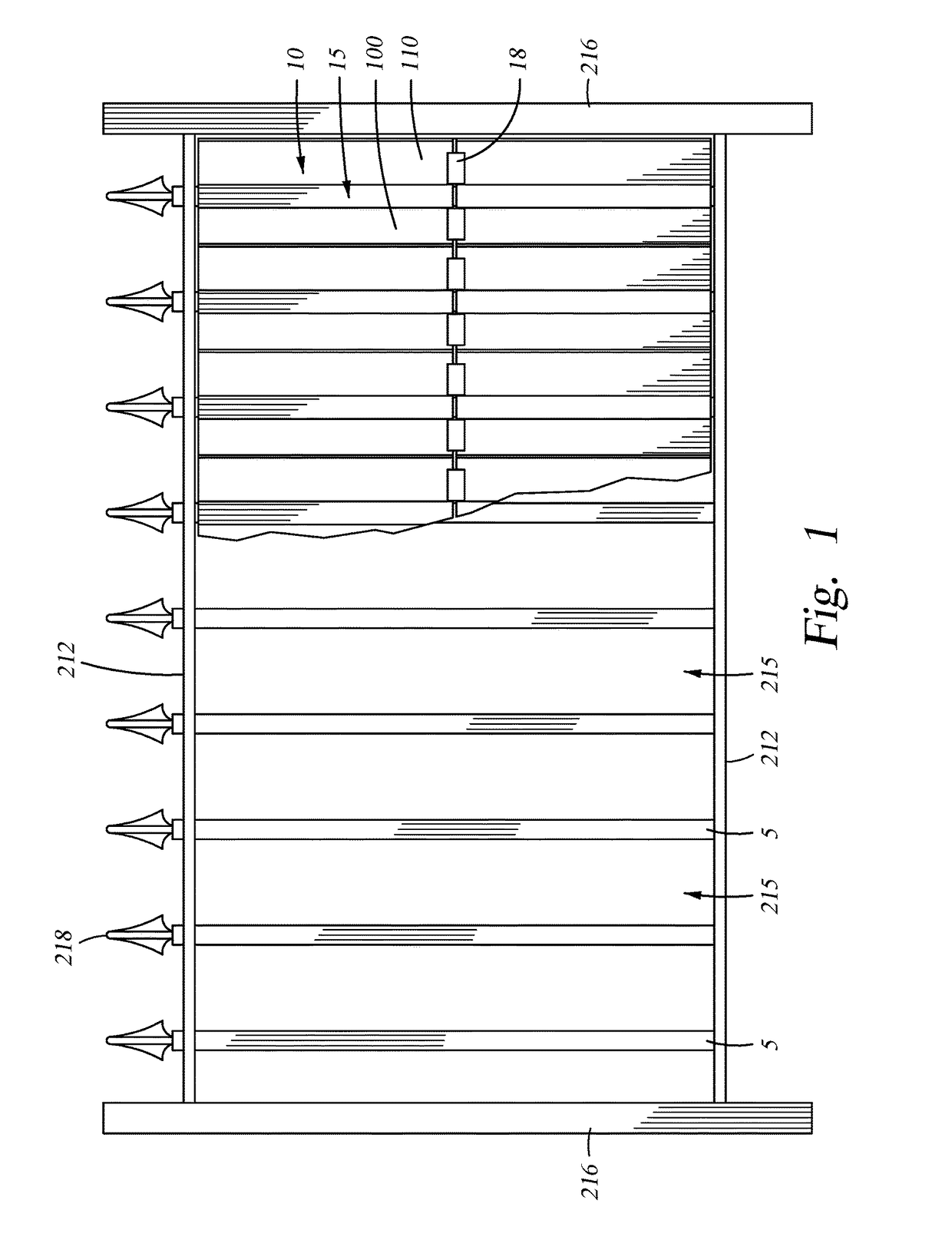
[0047]Generally, referring to the drawings, and particularly to FIG. 1, a segment of a conventional picket fence 210 is shown. Typically, a conventional picket fence 210 is constructed by excavating a hole. Posts 216 are placed in the hole with compacted so...


PUM


Abstract

An integrally formed panel (10) comprising an annular member (15) defining a longitudinally extending cavity (16) for engaging a picket (5); at least a first distal panel (100) extending away from the longitudinally extending cavity (16) for screening; the annular member (15) having a longitudinally extending slot (21) in communication with the longitudinally extending cavity (16) for receiving and releasing the picket 5; a locking tab (74) and an anchor lock (94) along opposite sides of the longitudinally extending slot (21) for releasably and tensionally securing the annular member (15) to the picket 5, the anchor lock (94) extending away from the longitudinally extending cavity (16) and projecting angularly from the adjoining portion of the annular member (15), and the locking tab (74) extending toward said anchor lock (94); a prying means 70 for receiving a lever and prying force to releasably latch the locking tab (74) and the anchor lock (94); at most one hinge (54) between the locking tab (74) and the anchor lock (94) for flexibly opening the annular member (15) to receive and release the picket (5); at most one corner (55) adjacent the locking tab (74) for cooperating with the hinge (54) to open the annular member (15) to receive and release the picket 5; a spring (51) between the corner (55) and the hinge (54) for tensioning the annular member (15); and an anchor flange 92 adjacent the anchor lock (94) extending into the longitudinally extending cavity (16) for anchoring the annular member (15) to the picket (5) and for resisting releasably latching the locking tab (74) to the anchor lock (94) during handling, shipping, or displaying.

Description

CROSS REFERENCE TO RELATED APPLICATIONS[0001]The following four (4) applications contain subject matter related to the present invention: 1) application Ser. No. 11 / 393,362 filed on or about Mar. 30, 2006; 2) application Ser. No. 11 / 642,083 filed on or about Dec. 20, 2006; 3) application Ser. No. 13 / 645,201 filed on or about Oct. 4, 2012; and 4) application serial number WO 2007 / 126983 filed on or about Mar. 29, 2007 which are incorporated by reference in their entirety.FEDERALLY SPONSORED RESEARCH[0002]Not Applicable.SEQUENCE LISTING OR PROGRAM[0003]Not Applicable.BACKGROUND OF THE INVENTION1. Field of the Invention[0004]This present invention relates to screening panels. More specifically, the present invention relates to a panel comprised of an annular member that is tensionally secured to a picket that may be easily installed and removed for optional screening.2. Description of the Related Art[0005]Screening panels have been known for many years. Such panels are fabricated, cast...

Claims


Application Information

Patent Timeline
IPC IPC(8): E04H17/16
CPCE04H17/16E04H17/1426E04H17/1602
Inventor NEFF, LAWRENCE MILLARD
Owner NEFF LAWRENCE MILLARD
Why Eureka
Try Eureka