
Submarine reconfigurable optical add/drop multiplexer with passive branching unit

a reconfigurable, multi-channel technology, applied in multiplex communication, electrical equipment, multiplex systems, etc., can solve the problems of increasing complexity of the bu, increasing the volume of the bu, and increasing the dynamic of the global communication network

Active Publication Date: 2017-11-07
NEC CORP
View PDF11 Cites 8 Cited by
  • Summary
  • Abstract
  • Description
  • Claims
  • Application Information

AI Technical Summary

Benefits of technology

This solution provides full reconfigurability, zero power consumption at branching units, high hardware reliability, secure data transmission, reduced hardware costs, and flexible network configurations, enabling efficient data transport with lower operational and hardware costs.

Problems solved by technology

However, a disadvantage of this arrangement is that the traffic in the global communication network is becoming more dynamic as internet-based traffic becomes more dominating.
However, each of the above-mentioned approaches includes drawbacks (e.g., limited quantity of BU configurations, added complexity to the BU, no full reconfigurability of BU, etc.), which are not desirable in submarine networks.

Method used


Image

  • Submarine reconfigurable optical add/drop multiplexer with passive branching unit
  • Submarine reconfigurable optical add/drop multiplexer with passive branching unit
  • Submarine reconfigurable optical add/drop multiplexer with passive branching unit

Examples


case 1

[0107] Trunk Heavy

[0108]In most submarine networks, the main trunks have more traffic than the branch paths. In other words, the traffic from a trunk terminal to a branch terminal does not exceed half of the channel capacity in the WDM system. For example, in a 40-channel WDM system, the traffic between a trunk terminal (such as A) and branch terminal (such as C) will not exceed 20 channels. We can further divide this case into two subcases.

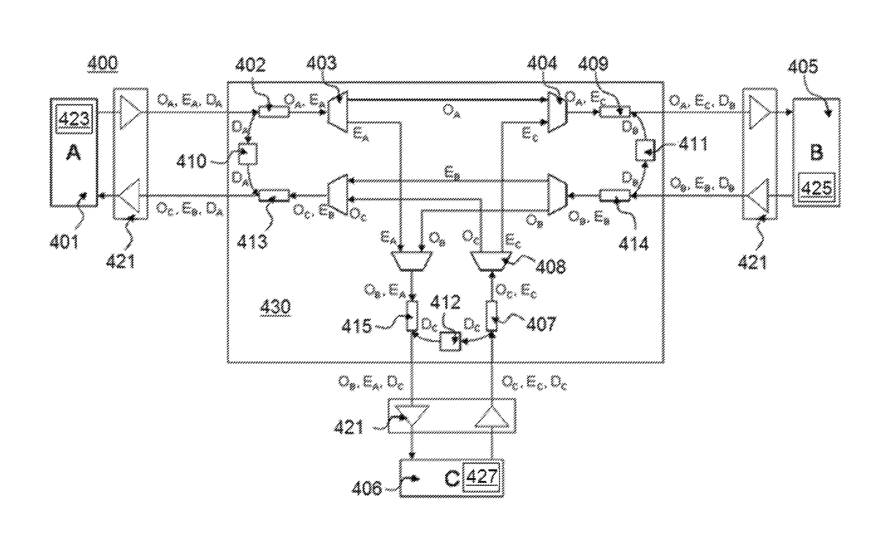
[0109]In the first subcase, the main trunks are fully occupied with useful WDM channels (for example, at the output of Trunk Terminal A, all WDM channels are present, and each one either goes to Trunk Terminal B 405 or to Branch Terminal C 406.). In fact, most of the existing BU architectures published so far assume this condition.

[0110]Under such condition, no dummy channel is required on the main trunk, therefore the dummy light filters (402, 413, 409, and 415) and the optical attenuator (410 and 411) at each trunk input / output of the BU 430 ca...

case 2

[0114] Asymmetric Branch Heavy

[0115]In one embodiment, as the submarine network traffic patterns becoming more dynamic, it is possible that some branch might have heavier load. In other words, the traffic between a trunk terminal and the branch might be more than the traffic between this trunk terminal and the other trunk terminal (such as AC traffic exceeds AB traffic), and might be more than half of the WDM channel capacity.

[0116]In such case, the two simplified architectures cannot be used. The two full architectures described above, however, can support such a case. Among them, the proposed architectures again show significant dummy light saving.

[0117]As discussed earlier, the 2 previously described architectures can be used for more general network arrangements than any conventional systems. Since they may not have a distinction between trunk and branch terminals, any traffic load balance setting among the terminals and the transmission links can be handled efficiently.

[0118]It...


PUM


Abstract

Systems and methods for data transport, including submarine reconfigurable optical add / drop multiplexers, branching units configured to receive signals from trunk terminals (TTs), and dummy light filters configured to pass useful signals through the filters, and to reflect dummy light. Optical interleavers are configured to separate useful signals into two or more groups of optical channels, and the optical channels are set to a frequency of either a left or a right portion of a total channel bandwidth. De-interleavers merge signal groups together from trunk terminals, and lasers at each of the transponders at the source terminals are configured to adjust a destination of a channel by fine tuning a frequency or wavelength of the one or more signals.

Description

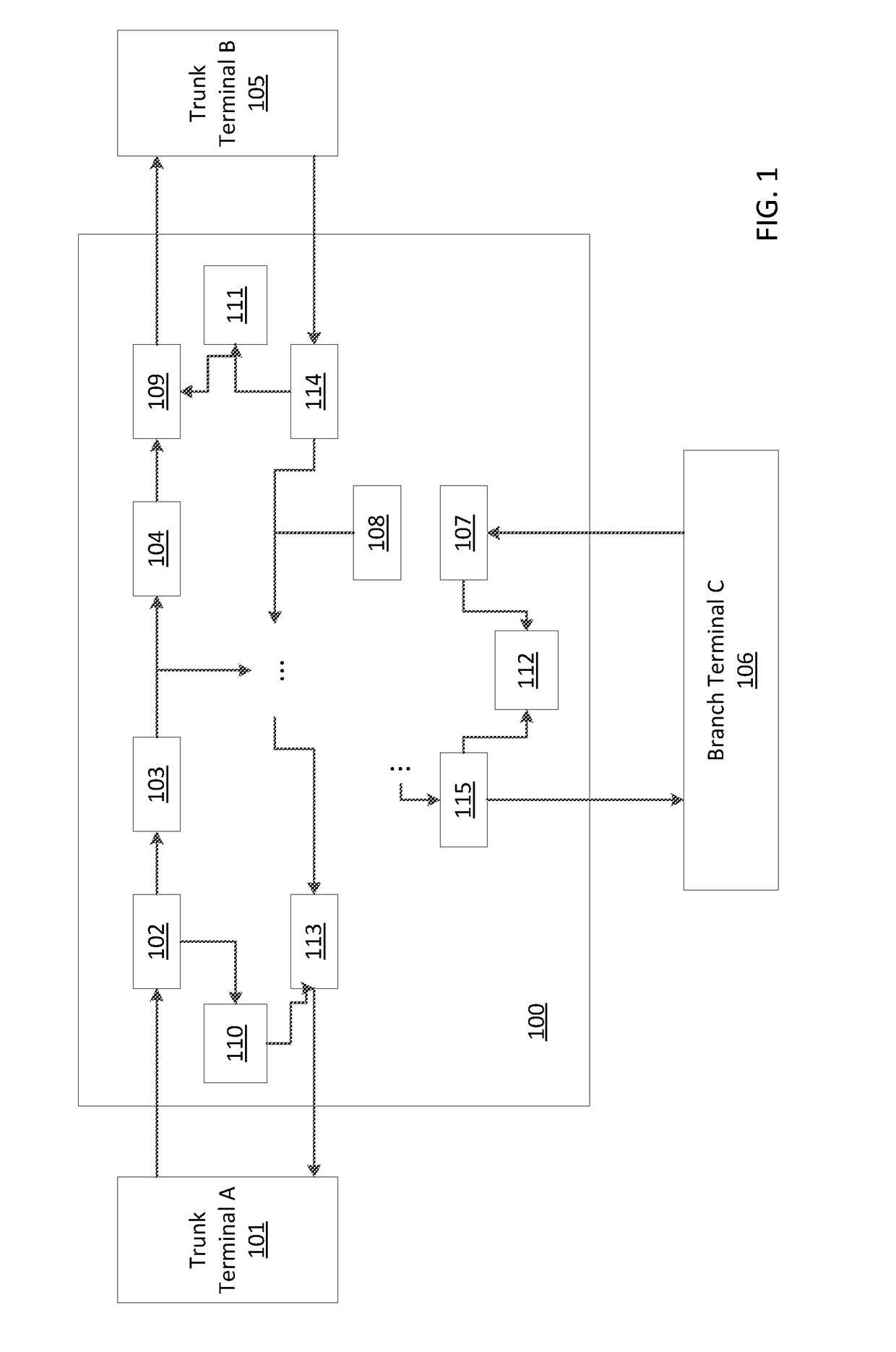
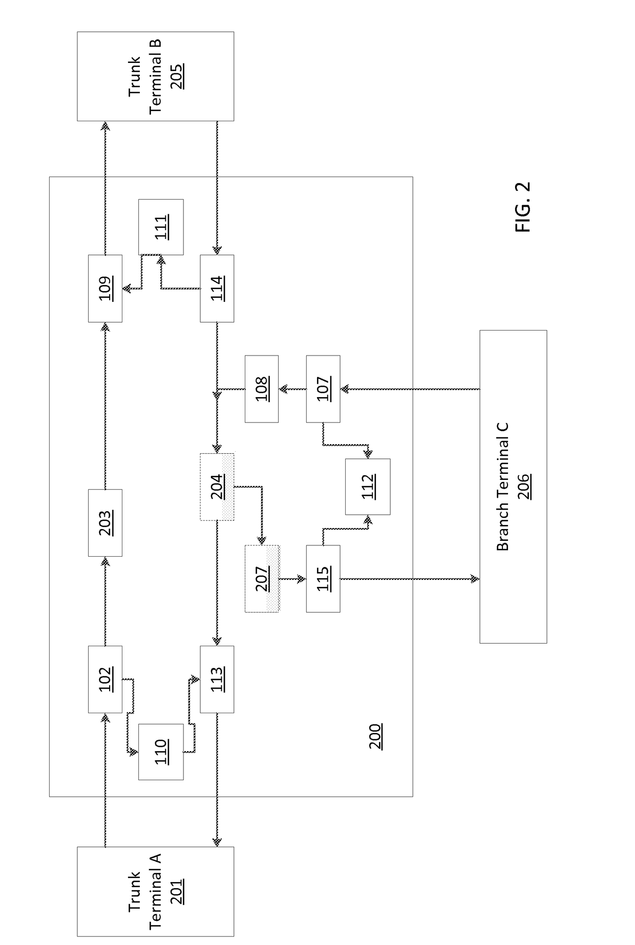
RELATED APPLICATION INFORMATION[0001]This application claims priority to provisional application Ser. No. 61 / 863,005 filed on Aug. 7, 2013, incorporated herein by reference.BACKGROUNDTechnical Field[0002]The present invention relates to submarine optical networks, and more particularly, to data transport using submarine reconfigurable optical add / drop multiplexing systems with passive branching units.Description of the Related Art[0003]Submarine optical networks form the backbone of global communication networks, and generally include main trunks that connect trunk terminals (e.g., point-to-point cable links with in-line optical amplifiers to boost the signal power), and branch paths which connect to other branch terminals. A branching unit (BU) is a network element that splits the signal between the main trunk and the branch path and vice versa. This allows the signals from different paths to share the same fiber instead of installing dedicated fiber pairs for each link. BUs genera...

Claims


Application Information

Patent Timeline
Patent Type & Authority Patents(United States)
IPC IPC(8): H04J14/02
CPCH04J14/021H04J14/0208H04J14/0205
Inventor JI, PHILIP N.AIDA, RYUJIWANG, TING
Owner NEC CORP
Learn More