Method of synchronizing a driving module and display apparatus performing the method

a technology of synchronizing a driving module and a display apparatus, which is applied in the direction of static indicating devices, instruments, agriculture tools and machines, etc., can solve the problems of abnormal display of images to the liquid crystal display apparatus, waterfall defects and charge rate defects, etc., to improve the display quality of high-resolution images, reduce the number of the terminal of the connector which connects between adjacent printed circuit boards, and reduce the number of the pin of the timing controller

Active Publication Date: 2017-11-14
SAMSUNG DISPLAY CO LTD
View PDF17 Cites 0 Cited by
  • Summary
  • Abstract
  • Description
  • Claims
  • Application Information

AI Technical Summary

Benefits of technology

[0010]Exemplary embodiments of the invention provide a method of synchronizing a driving module of a display device for improving a display quality and simplifying a circuit design.
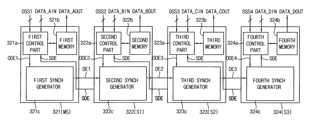
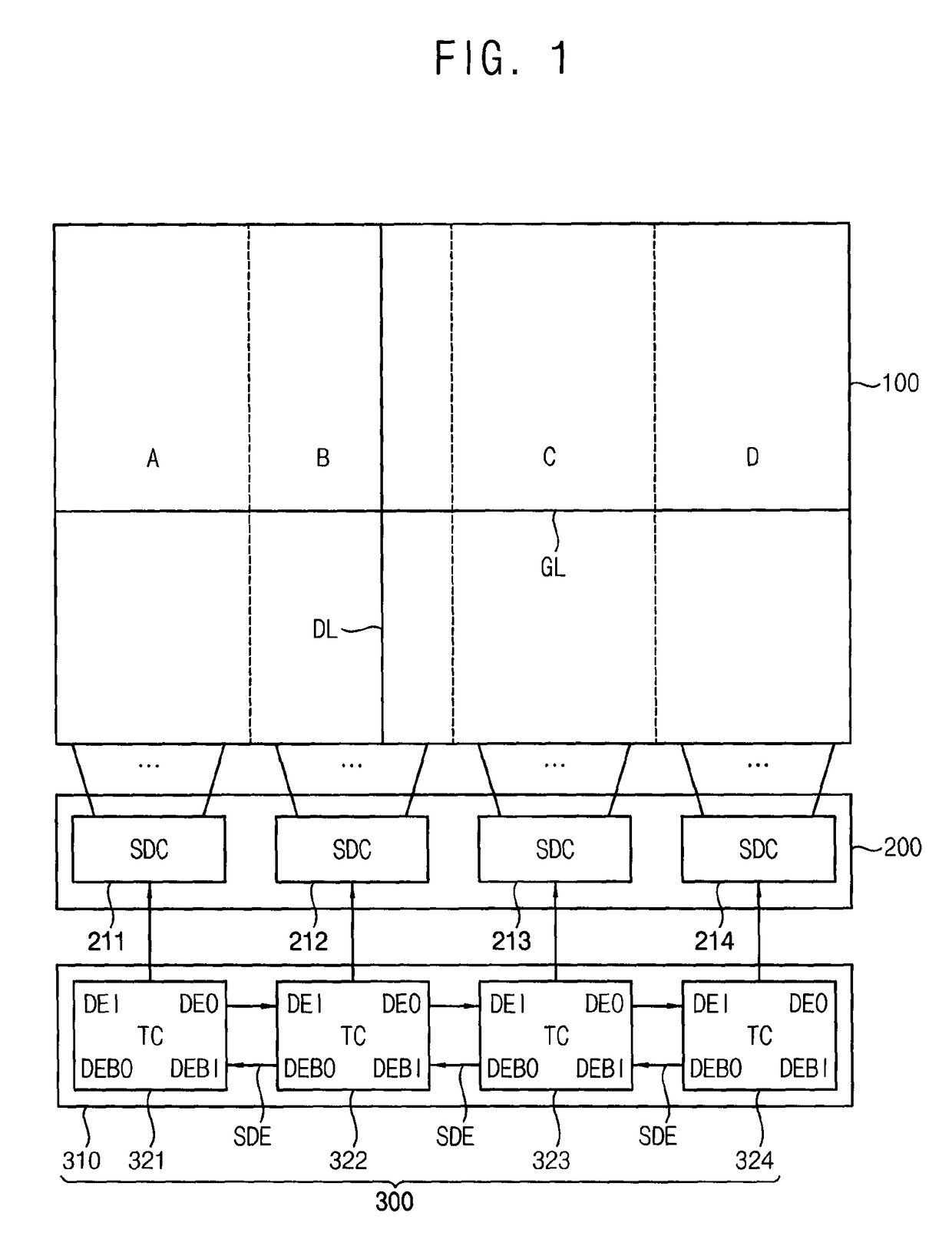
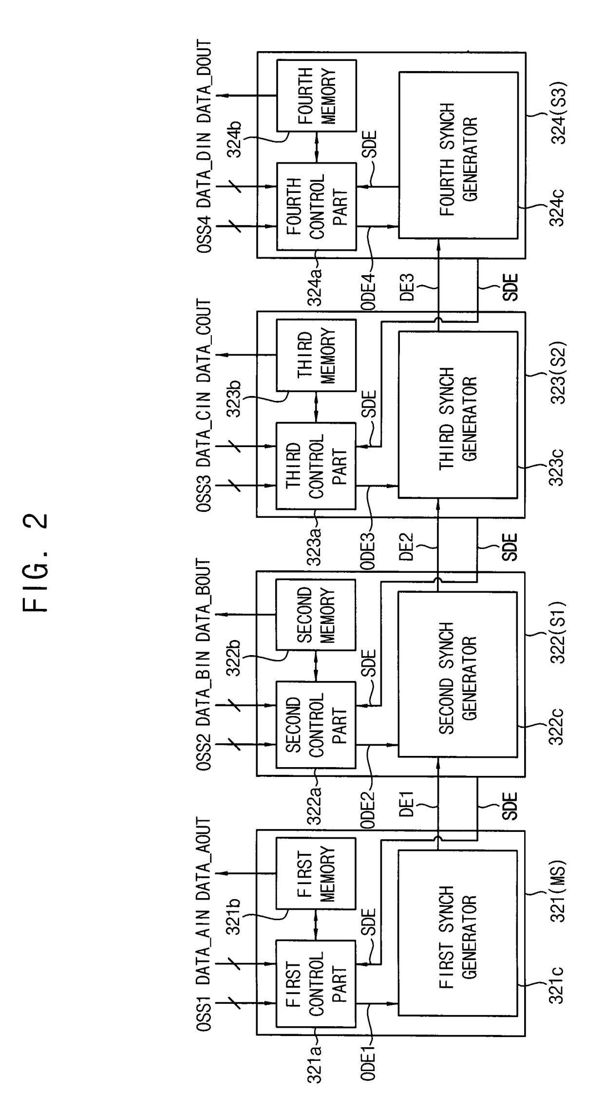
[0032]According to exemplary embodiments of the invention, the plurality of timing controllers is synchronized based on the synch DE signal, which is delayed by a predetermined period from the earliest signal among the original DE signals of the timing controllers, such that the data synchronization of the timing controllers may be effectively achieved. Therefore, a display quality of a high-resolution image may be improved by the data synchronization. In such embodiments, the timing controller may be achieved the data synchronization only using two input pins and two output pins. Thus, the number of the pin of the timing controller may be decreased and the number of the terminal of the connector which connects between adjacent printed circuit boards may be decreased. Therefore, the circuit design of the control driving module may be simplified.

Problems solved by technology

In a driving device in a multi-chip structure included in a display device and used for high-speed frame driving method, when synchronization between the chips is not matched, an image may be abnormally displayed to the liquid crystal display apparatus, and waterfall defects and charge rate defects may occur.

Method used


Image

  • Method of synchronizing a driving module and display apparatus performing the method
  • Method of synchronizing a driving module and display apparatus performing the method
  • Method of synchronizing a driving module and display apparatus performing the method

Examples


Embodiment Construction

[0041]The invention now will be described more fully hereinafter with reference to the accompanying drawings, in which various embodiments are shown. This invention may, however, be embodied in many different forms, and should not be construed as limited to the embodiments set forth herein. Rather, these embodiments are provided so that this disclosure will be thorough and complete, and will fully convey the scope of the invention to those skilled in the art. Like reference numerals refer to like elements throughout.

[0042]It will be understood that when an element is referred to as being “on” another element, it can be directly on the other element or intervening elements may be therebetween. In contrast, when an element is referred to as being “directly on” another element, there are no intervening elements present.

[0043]It will be understood that, although the terms “first,”“second,”“third” etc. may be used herein to describe various elements, components, regions, layers and / or se...


PUM


Abstract

A method of synchronizing a driving module includes applying a plurality of original data enable (“DE”) signals to a plurality of timing controller of the driving module, respectively, generating a synch DE signal from the driving module based on the earliest signal among the original DE signals, and transferring the synch DE signal to the plurality of timing controllers in a cascade mode.

Description

[0001]This application claims priority to Korean Patent Application No. 10-2014-0001841, filed on Jan. 7, 2014, and all the benefits accruing therefrom under 35 U.S.C. §119, the content of which in its entirety is herein incorporated by reference.BACKGROUND[0002]1. Field[0003]Exemplary embodiments of the invention relate to a method of synchronizing a driving module and a display apparatus performing the method. More particularly, exemplary embodiments of the invention relate to a method of synchronizing a driving module for simplifying a circuit design and a display apparatus performing the method.[0004]2. Description of the Related Art[0005]Recently, a liquid crystal display (“LCD”) apparatus has been widely used in application technologies, such as computer games using high-resolution videos and three-dimensional (“3D”) images.[0006]In such an LCD apparatus, a motion interpolation frame may be inserted between a present frame and a previous frame to decrease motion blur in a high...

Claims


Application Information

Patent Timeline
Patent Type & Authority Patents(United States)
IPC IPC(8): H04N13/04G09G5/12G09G3/36G09G3/00G06F3/14
CPCG09G3/36G09G3/3666G09G5/12G09G2356/00G09G3/003G09G2300/026G09G2300/0426G06F3/1446A01D46/20B66F11/044
Inventor SOHN, YOUNG-SOOYOON, KI-TAEJEON, JAE-GWANTAKEGAMA, AKIHIRO
Owner SAMSUNG DISPLAY CO LTD
Why Eureka
Try Eureka