Multi-additive delivery system

a technology of additives and delivery systems, applied in chemical apparatus and processes, thin material processing, chemical/physical/physical-chemical processes, etc., can solve the problems of large additive tank waste, and relative difficulty in switching to a different additive in order to produce a different produ

Active Publication Date: 2017-11-21
DOW GLOBAL TECH LLC
View PDF28 Cites 4 Cited by
  • Summary
  • Abstract
  • Description
  • Claims
  • Application Information

AI Technical Summary

Benefits of technology

[0015]The present invention is, in general, a multi-additive delivery system offering important advantages over previous, hard-piped systems that were designed to enable delivery of a single additive, e.g., a catalyst, co-catalyst, scavenger, or other reaction- or product-modifying additives to a reaction or mixing site. Such reaction or mixing site may be, in non-limiting embodiments, a polymerization or other type of vessel. In particular, the invention enables simplified delivery of one or more additives to the vessel directly, without requiring intermediate, extended-time additive storage and / or mix tanks. The delivery is desirably automated to enable simultaneously controlling the flow rate of, potentially, several components (e.g., catalyst, co-catalyst, scavenger), enabling faster and more efficient transitions from one additive or additive family to another. Such transitions may also be thereby made inherently safer, because of the capability to also control line-flushings using the same automated means. Furthermore, diluents (solvents) may be added easily to the system to improve dissolution of the additive or additives and improve flow control; additive types may be “swung on the fly” (without shutting down the operation); and empty additive containers likewise replenished without shutdown. These advantages and the means and methods of their attainment will be described further hereinbelow.

Problems solved by technology

Unfortunately, the above-described arrangement has certain drawbacks.
Another drawback is that it is relatively difficult to switch to a different additive in order to produce a different product.
In some instances, it may be necessary to waste large proportions of tanks of additives where only a small amount is needed for a production run.
Alternatively, a whole new production line may be needed, which is very expensive.
A third drawback is that it is also difficult or impossible to customize, or experiment to customize, a variety of additives.
In particular, it is difficult to customize such “on the fly,” i.e., during operation, meaning without shutting down the production line as a whole and installing temporary tubing of some type.

Method used


Image

  • Multi-additive delivery system
  • Multi-additive delivery system

Examples


example

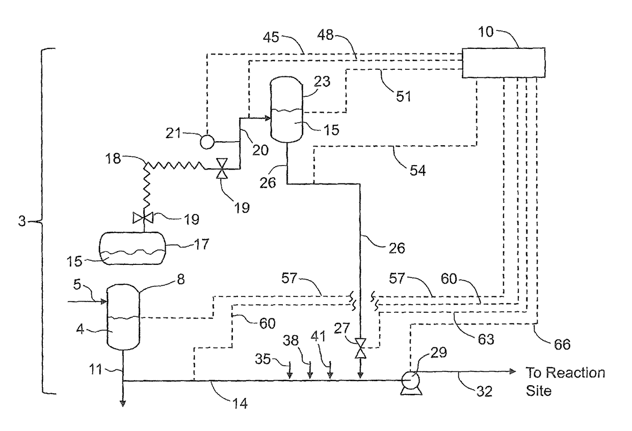
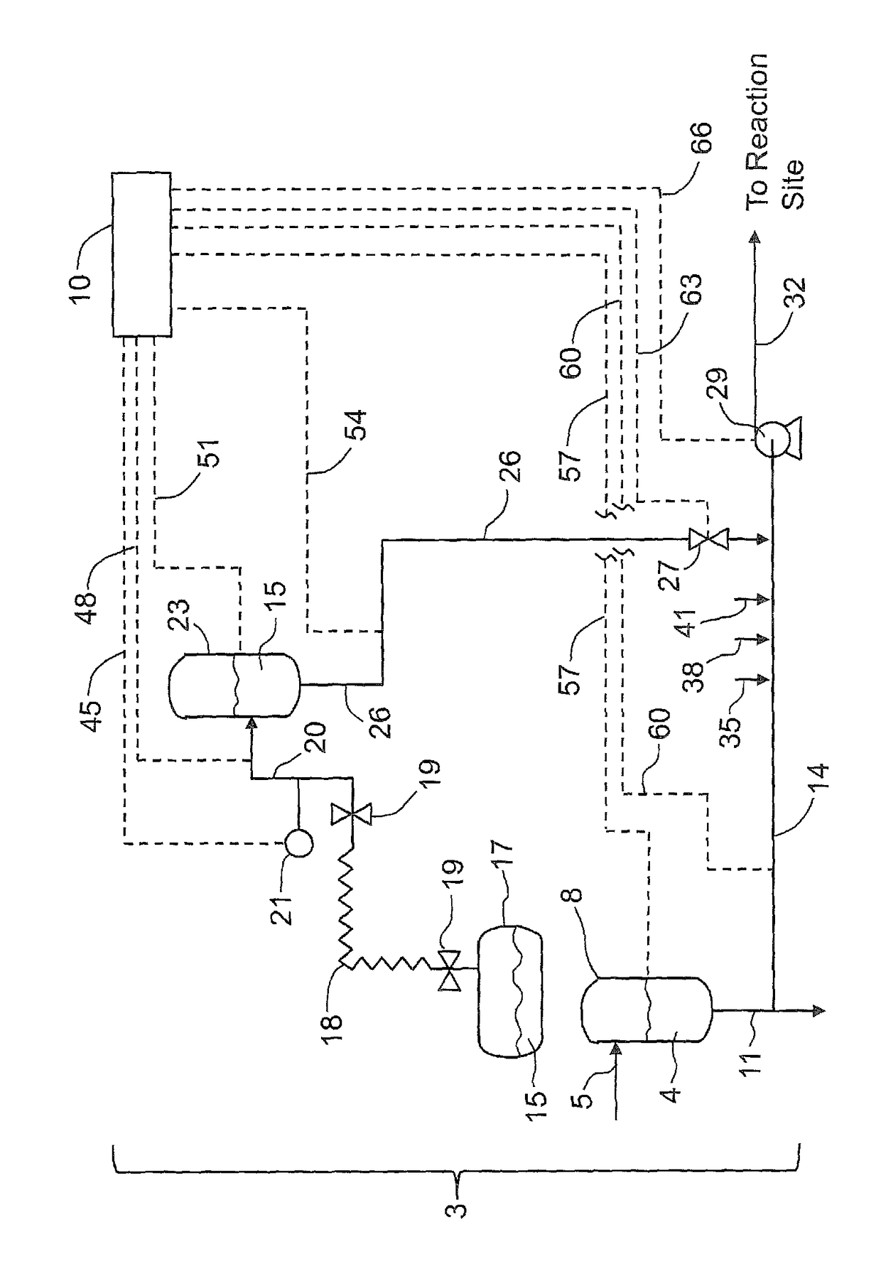
[0027]This Example refers to FIG. 1. FIG. 1 is a schematic diagram of one embodiment of the invention, showing a system to deliver either just one additive at a time to a reaction site, but enabling convenient switching between two or more additive sources under conditions such as, for example, exhaustion of one of the sources. As has been described hereinabove, however, any number of such systems may feed into a single given reactor.

[0028]The overall additive delivery system is designated as numeral 3. In this system, a solvent 4 is delivered via solvent source line 5 to solvent tank 8, which is controlled by process controller 10. This solvent 4 then feeds into solvent line 11 (which also potentially feeds to other additive systems, as suggested by the arrow on solvent additive line 11) and from there into additive line 14.

[0029]Essentially concurrently with the solvent movement into and through additive line 14, a desired additive 15, which has been pre-loaded into a (portable) a...


PUM


Abstract

An apparatus and method for delivery of additives(s), e.g., catalyst, co-catalyst, scavengers, and / or other reaction- or product-modifying agents, to a reaction or mixing site, such as a reaction vessel, offers the capability for multi-additive delivery and customization of additive selection, flow and flow rate, and if desired, mixing thereof, without production train shutdowns. The invention includes at least two additive sources that are detachably connected, with conduit, to the reaction or mixing site, and a process control means, preferably automated, that is capable of initiating, terminating, and determining the rate of flow from the additive sources.

Description

REFERENCE TO RELATED APPLICATIONS[0001]The present application claims the benefit of U.S. Provisional Application No. 61 / 645,415, filed on May 10, 2012 and is a national stage of International Application No. PCT / US2013 / 037281, filed Apr. 19, 2013, now WO 2013 / 169466. The contents of the aforementioned applications are incorporated herein by reference in their entirety.BACKGROUND[0002]Field of the Invention[0003]The invention relates to methods and apparatuses for delivering additives to reacting materials. More particularly, it relates to methods and apparatuses for enabling operations wherein reaction-modifying additives can be substituted and / or combined quickly, easily, and in a customizable fashion.[0004]Background of the Invention[0005]In many commercial production facilities today, additive feed systems are permanently hard-piped to a mixing and / or reaction site, such as a reaction vessel. This enables the selected additive, or mixture of additives, to be fed into the site at...

Claims


Application Information

Patent Timeline
Patent Type & Authority Patents(United States)
IPC IPC(8): B01J19/00B01J19/24
CPCB01J19/0006Y10T137/0318B01J2219/00761B01J2219/00164B01J4/02B01J2204/002
Inventor CERK, FRANK J.JAIN, JR., PRADEEPDIRK, MICHELLE D.BOONE, HAROLD W
Owner DOW GLOBAL TECH LLC
Why Eureka
Try Eureka