
Head mounted display

a display and head technology, applied in the field of head mounted displays, can solve the problems affecting the comfort and wear of the observer, and achieve the effect of improving the comfort and wear and reducing the horizontal area of the head mounted display

Active Publication Date: 2017-11-28
DELTA ELECTRONICS INC
View PDF24 Cites 7 Cited by
  • Summary
  • Abstract
  • Description
  • Claims
  • Application Information

AI Technical Summary

Benefits of technology

The patent describes a head mounted display that can provide a more comfortable and convenient way to wear it. The display uses two different images that are combined in the observer's brain to create a stereoscopic image. The display also reduces the horizontal area, making it smaller and more portable.

Problems solved by technology

However, a conventional head mounted display has a complex structure, a huge size and a heavy weight, which may affect wearing convenience and comfort of the observer.

Method used


Image

  • Head mounted display
  • Head mounted display
  • Head mounted display

Examples


Embodiment Construction

[0014]Reference will now be made in detail to the present embodiments of the invention, examples of which are illustrated in the accompanying drawings. Wherever possible, the same reference numbers are used in the drawings and the description to refer to the same or like parts.

[0015]Further, spatially relative terms, such as “beneath,”“below,”“lower,”“above,”“upper” and the like, may be used herein for ease of description to describe one element or feature's relationship to another element(s) or feature(s) as illustrated in the figures. The spatially relative terms are intended to encompass different orientations of the device in use or operation in addition to the orientation depicted in the figures. The apparatus may be otherwise oriented (rotated 90 degrees or at other orientations) and the spatially relative descriptors used herein may likewise be interpreted accordingly. Furthermore, the term “device A is optically coupled to device B” indicates a light from or through the devi...


PUM


Abstract

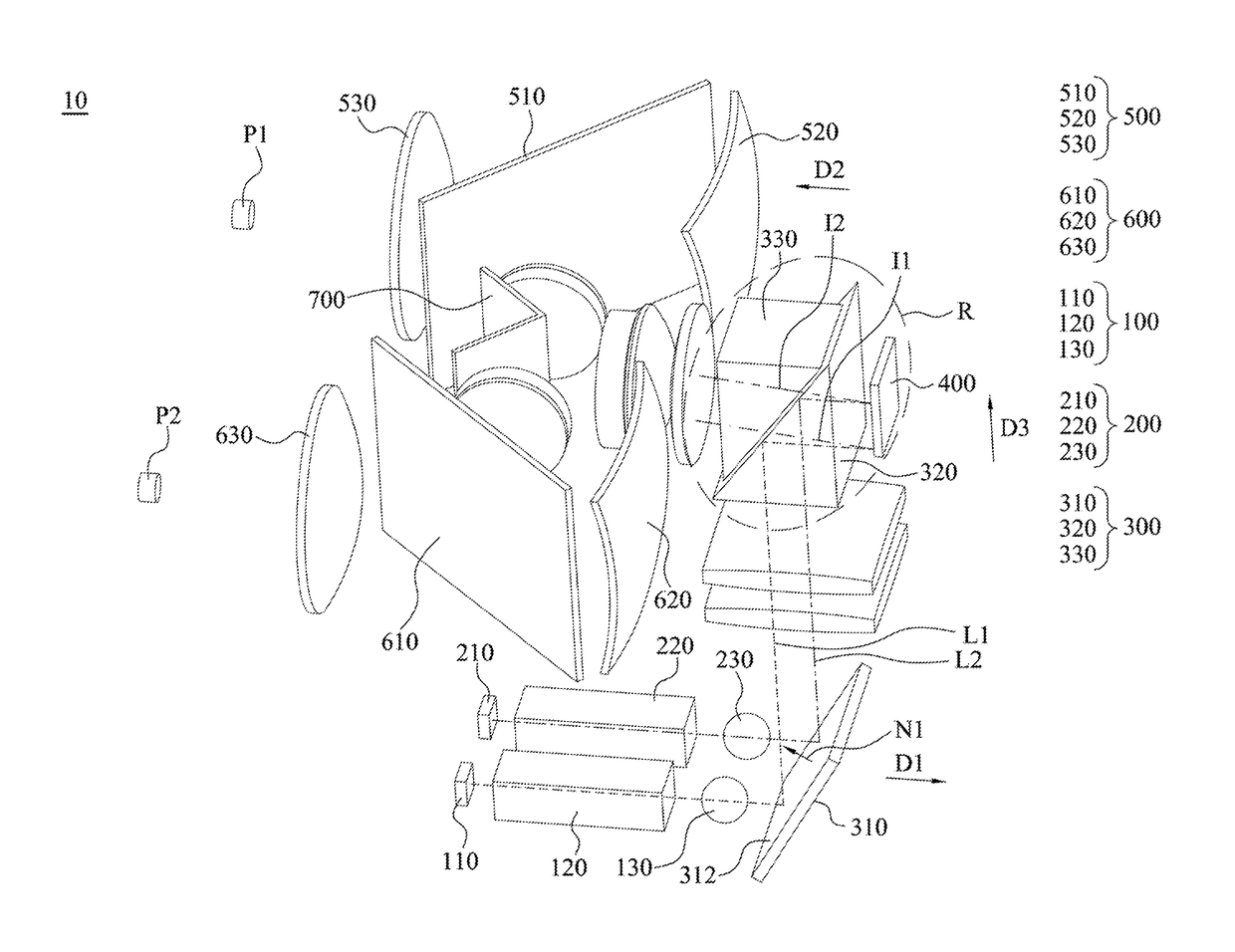
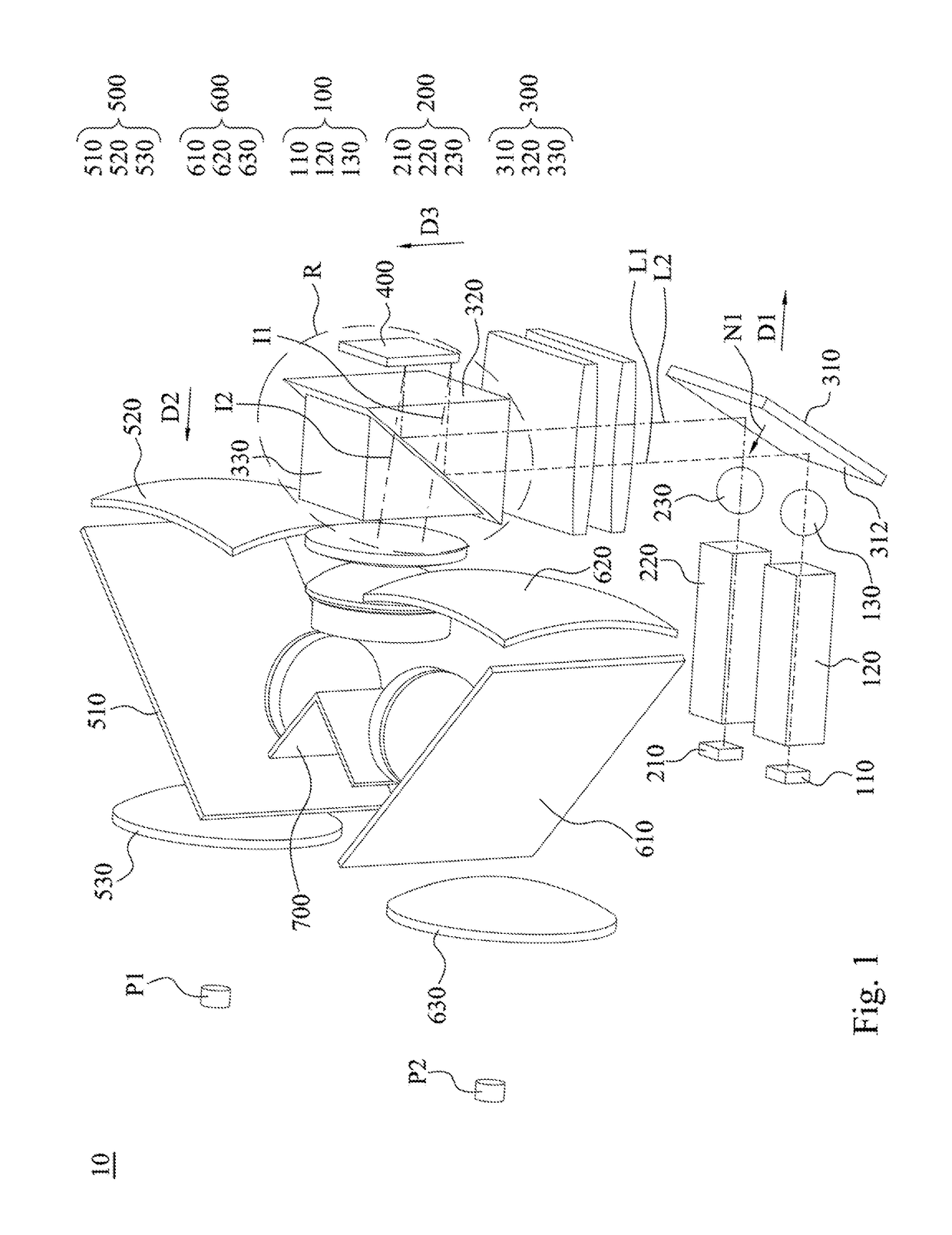
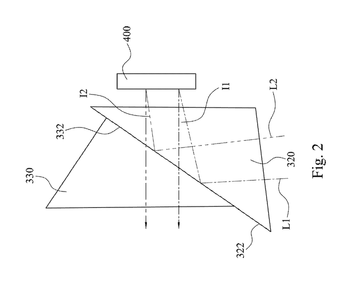
A head mounted display includes first and second light source modules, a light reversely turning module, an image output module, first and second eyepiece modules, and a beam splitting mirror. The first and second light source modules are respectively configured to emit first and second lights. The image output module is configured to receive the first and second lights, generating first and second image lights with corresponding image information respectively. The light reversely turning module is optically coupled between the first light source module (or the second light source module) and the image output module, making a propagating direction of the first light (or the second light) in reverse to that of the first image light (or the second light). The beam splitting mirror is optically coupled between the image output module and the first / second eyepiece module, guiding the first / second image light into the first / second eyepiece module.

Description

RELATED APPLICATIONS[0001]This application claims priority to Taiwan Application Serial Number 105116194, filed May 25, 2016, which is herein incorporated by reference.BACKGROUNDTechnical Field[0002]The present disclosure relates to a head mounted display. More particularly, the present disclosure relates to a stereo head mounted display.Description of Related Art[0003]In recent years, with the increasing development of virtual reality technology, an optical product which can show a stereoscopic image has become a focal point in the consumer market. Conventionally, a head mounted display can respectively provide different images to two eyes of an observer, and the eyes of the observer can respectively receive different image information, so that the observer can perceive a stereoscopic image by exploiting the binocular parallax of typical human sight. However, a conventional head mounted display has a complex structure, a huge size and a heavy weight, which may affect wearing conven...

Claims


Application Information

Patent Timeline
Patent Type & Authority Patents(United States)
IPC IPC(8): G02B27/01G02B27/22G02B25/00G02B27/14G02B26/08
CPCG02B27/2264G02B27/2235G02B25/001G02B27/14G02B26/0833G02B27/01G02B27/0172G02B27/143G02B2027/0134G02B2027/0136G02B30/24G02B30/35
Inventor HUANG, JUNE-JEI
Owner DELTA ELECTRONICS INC
Learn More