
Time domain level adjustment for audio signal decoding or encoding

a time domain and audio signal technology, applied in the field of audio signal encoding, decoding, and processing, can solve the problems of small deviations in signal amplitude and phase with respect to original waveform, and signal at the receiver side is only regenerated with correct power, so as to reduce the probability of clipping and the overall loudness level of the audio signal.

Active Publication Date: 2017-11-28
FRAUNHOFER GESELLSCHAFT ZUR FOERDERUNG DER ANGEWANDTEN FORSCHUNG EV
View PDF24 Cites 40 Cited by
  • Summary
  • Abstract
  • Description
  • Claims
  • Application Information

AI Technical Summary

Benefits of technology

The patent describes a way to shift frequency signals in an audio representation without losing important information. By shifting the signals to a certain level during periods when the overall loudness level is high, a limited word length converter can be used. This helps to reduce the likelihood of clipping and also reduces the impact of noise on the overall quality of the audio signal.

Problems solved by technology

Challenges arise as modern perceptual audio codecs are necessitated to deliver satisfactory audio quality at increasingly low bit rates.
This may lead to audible artifacts (clicks or short distortion).
Quantization errors in the frequency domain result in small deviations of the signal amplitude and phase with respect to the original waveform.
Consequently, the signal at the receiver side is only regenerated with correct power but without waveform preservation.
Signals with an amplitude close to full scale are prone to clipping.
In general, this might lead to clipping, if the audio signal is encoded at sufficiently high levels and transmitted normalization gains suggest increasing loudness levels.
Unfortunately, prior to the limiter, sufficient headroom (in terms of dynamic range and / or bit resolution) is necessitated.
Further, due to poor quantization or parametric description, any coded audio signal might go into clipping if the original audio was mastered at levels near the clipping threshold.

Method used


Image

  • Time domain level adjustment for audio signal decoding or encoding
  • Time domain level adjustment for audio signal decoding or encoding
  • Time domain level adjustment for audio signal decoding or encoding

Examples


Embodiment Construction

[0041]Audio processing has advanced in many ways and it has been subject of many studies, how to efficiently encode and decode an audio data signal. Efficient encoding is, for example, provided by MPEG AAC (MPEG=Moving Pictures Expert Group; AAC=Advanced Audio Coding). Some aspects of MPEG AAC are explained in more detail below, as an introduction to audio encoding and decoding. The description of MPEG AAC is to be understood as an example only, as the described concepts may be applied to other audio encoding and decoding schemes, as well.

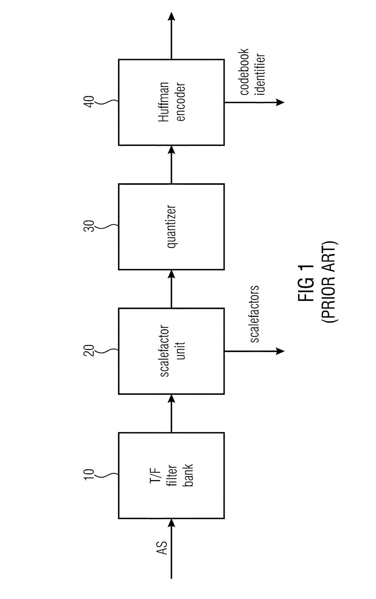
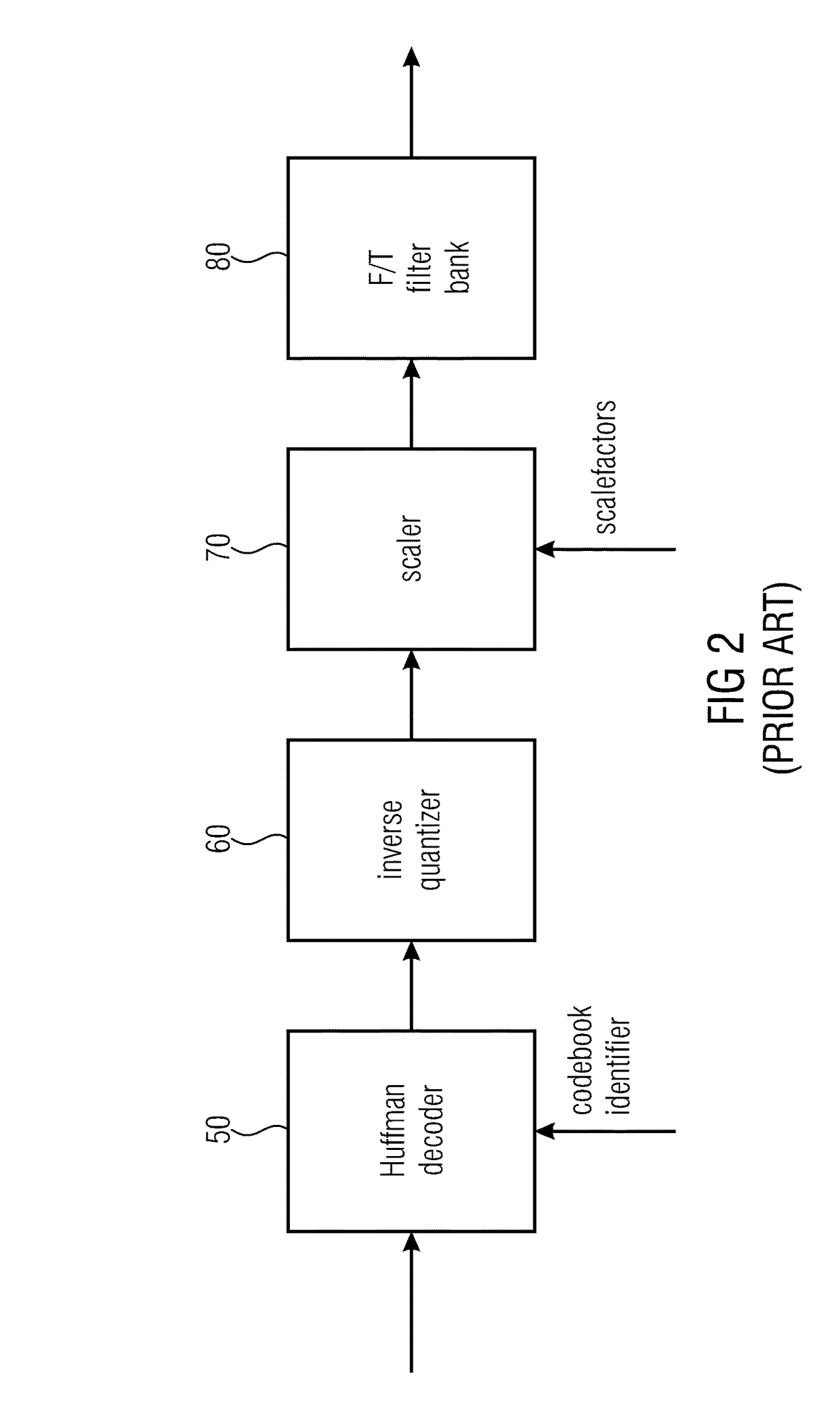
[0042]According to MPEG AAC, spectral values of an audio signal are encoded employing scalefactors, quantization and codebooks, in particular Huffman Codebooks.

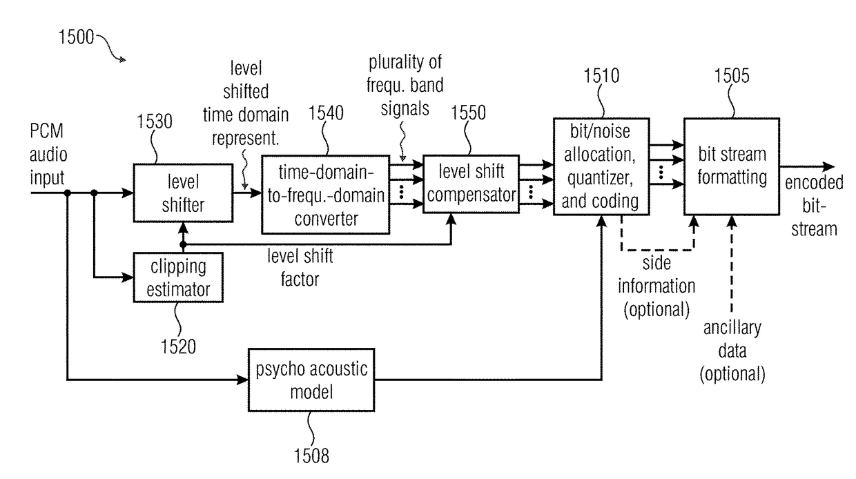
[0043]Before Huffman encoding is conducted, the encoder groups the plurality of spectral coefficients to be encoded into different sections (the spectral coefficients have been obtained from upstream components, such as a filterbank, a psychoacoustical model, and a quantizer controlled by th...


PUM


Abstract

An audio signal decoder for providing a decoded audio signal representation on the basis of an encoded audio signal representation has a decoder preprocessing stage for obtaining a plurality of frequency band signals from the encoded audio signal representation, a clipping estimator, a level shifter, a frequency-to-time-domain converter, and a level shift compensator. The clipping estimator analyzes the encoded audio signal representation and / or side information relative to a gain of the frequency band signals in order to determine a current level shift factor. The level shifter shifts levels of the frequency band signals according to the level shift factor. The frequency-to-time-domain converter converts the level shifted frequency band signals into a time-domain representation. The level shift compensator acts on the time-domain representation for at least partly compensating a corresponding level shift and for obtaining a substantially compensated time-domain representation.

Description

CROSS-REFERENCE TO RELATED APPLICATIONS[0001]This application is a continuation of co-pending International Application No. PCT / EP2014 / 050171, filed Jan. 7, 2014, which is incorporated herein by reference in its entirety, and additionally claims priority from European Application No. 13151910.0, filed Jan. 18, 2013, which is also incorporated herein by reference in its entirety.BACKGROUND OF THE INVENTION[0002]The present invention relates to audio signal encoding, decoding, and processing, and, in particular, to adjusting a level of a signal to be frequency-to-time converted (or time-to-frequency converted) to the dynamic range of a corresponding frequency-to-time converter (or time-to-frequency converter). Some embodiments of the present invention relate to adjusting the level of the signal to be frequency-to-time converted (or time-to-frequency converted) to the dynamic range of a corresponding converter implemented in fixed-point or integer arithmetic. Further embodiments of the...

Claims


Application Information

Patent Timeline
Patent Type & Authority Patents(United States)
IPC IPC(8): G10L19/00G10L19/02G10L19/005G10L21/00G10L21/0224G10L21/034G10L21/0232G10L21/0332
CPCG10L19/005G10L19/0017G10L19/02G10L21/0332G10L21/0232G10L21/034G10L21/0224G10L19/00G10L19/0018
Inventor SCHREINER, STEPHANBORSUM, ARNENEUSINGER, MATTHIASJANDER, MANUELLOHWASSER, MARKUSNEUGEBAUER, BERNHARD
Owner FRAUNHOFER GESELLSCHAFT ZUR FOERDERUNG DER ANGEWANDTEN FORSCHUNG EV
Learn More