Planar heat pipe with architected core and vapor tolerant arterial wick

a heat pipe and core technology, applied in indirect heat exchangers, lighting and heating apparatus, etc., can solve the problems of affecting the function of arterial wicks, requiring very little maintenance, and requiring arterial wicks to experience blockages

Active Publication Date: 2017-12-05
HRL LAB
View PDF30 Cites 34 Cited by
  • Summary
  • Abstract
  • Description
  • Claims
  • Application Information

AI Technical Summary

Benefits of technology

[0010]According to an embodiment of the present invention, a planar heat pipe includes an arterial wick structure enabling venting or trapping of vapor bubbles which may occur in and otherwise block the artery, thus enabling higher heat fluxes than may be possible with known wick structure designs.

Problems solved by technology

Because heat pipes contain no mechanical moving parts, they typically require very little maintenance.
While these arterial wick structures are optimized for heat pipes requiring higher performance where, for example, the working fluid must travel a long distance between hot portion and cold portion or a large axial heat flux is imposed, known arterial wick structures often experience blockages caused by vapor bubbles.
More specifically, vapor bubbles often form in the arteries of arterial wick structures, causing arterial function to cease and greatly reduce the maximum heat flux of the heat pipe.
However, these same arterial wick structures are not as easily accommodated in planar pipes—which typically utilize homogenous wicks or vapor chambers—with little to no space to separate out the arteries from the interior walls of the heat pipe.
As such, the risk of vapor bubbles nucleating in the arteries of planar heat pipes is greatly increased.
Addition of mechanical members, however, increases pressure loss of the vapor, thus reducing maximum heat flux through these areas of the heat pipe.

Method used


Image

  • Planar heat pipe with architected core and vapor tolerant arterial wick
  • Planar heat pipe with architected core and vapor tolerant arterial wick
  • Planar heat pipe with architected core and vapor tolerant arterial wick

Examples


Embodiment Construction

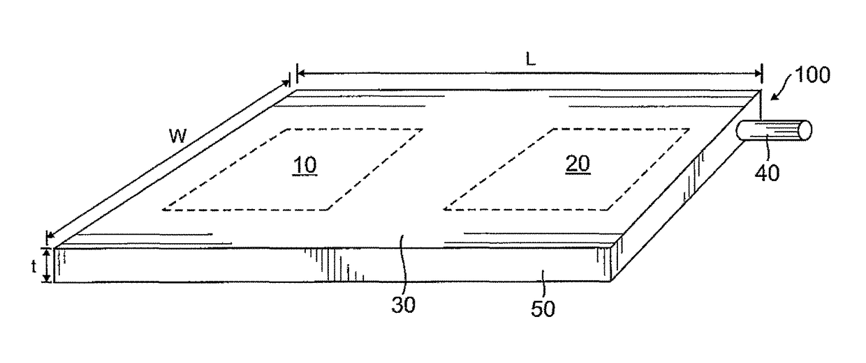
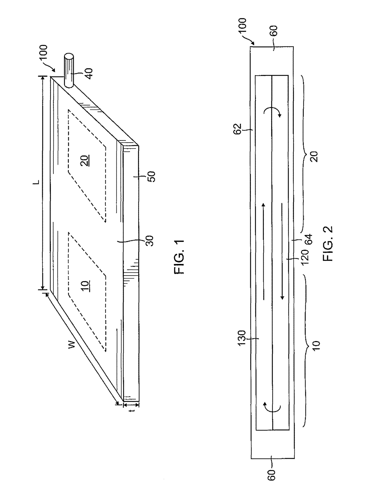
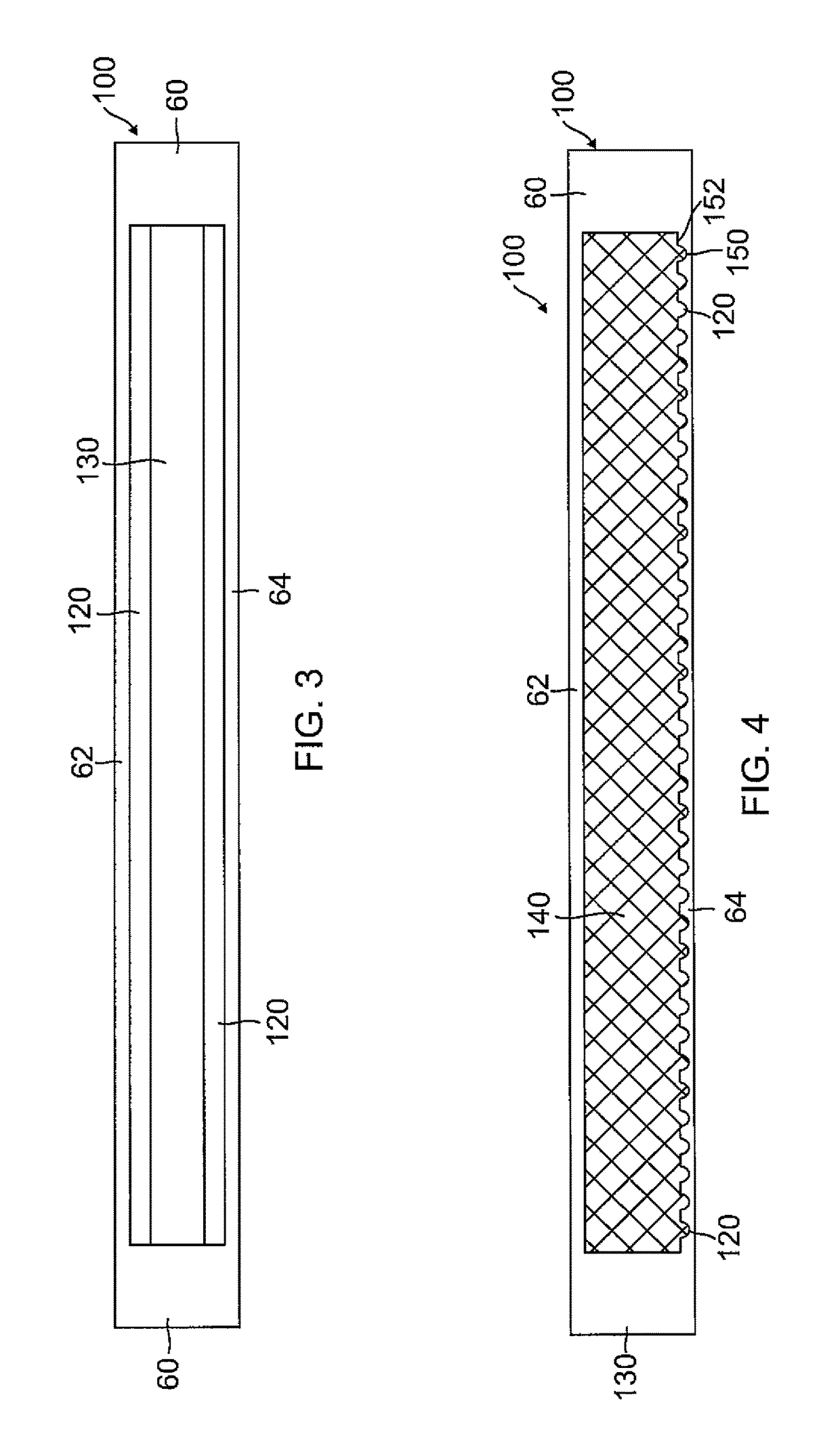
[0065]The detailed description set forth below in connection with the accompanying drawings is intended as a description of embodiments of a planar heat pipe with architected core and vapor tolerant arterial wick, as provided in accordance with the present invention, and is not intended to represent the only forms in which the present invention may be constructed or utilized. The description sets forth the features of the present invention in connection with the illustrated embodiments. It is to be understood, however, that the same or equivalent functions and structures may be accomplished by different embodiments that are also intended to be encompassed within the spirit and scope of the invention. As denoted elsewhere herein, like element numbers are intended to indicate like elements or features.

[0066]A heat pipe 100 according to an embodiment of the present invention will be described with reference to FIGS. 1 and 2, in which FIG. 1 is a perspective view illustrating the planar...


PUM

PropertyMeasurementUnit
thicknessaaaaaaaaaa
thicknessaaaaaaaaaa
thicknessaaaaaaaaaa

Abstract

A planar heat pipe for transferring heat between a higher temperature region and a lower temperature region includes a bottom facesheet, a top facesheet, a vapor-venting arterial wick between the bottom facesheet and the top facesheet and including a high permeability layer and a high capillary pressure layer each having pores such that an average pore hydraulic diameter in the high permeability layer is greater than an average pore diameter in the high capillary pressure layer. The pipe also includes an architected mechanical core structure between the arterial wick and the top facesheet, and a working fluid between the bottom facesheet and the top facesheet. The architected mechanical core structure may have a vapor region, and the vapor-venting arterial wick may have a liquid region.

Description

CROSS-REFERENCE TO RELATED APPLICATION[0001]This application claims priority to and the benefit of U.S. Provisional Application No. 61 / 801,638, filed on Mar. 15, 2013, the entire content of which is incorporated herein by reference.FIELD[0002]The present invention relates generally to planar heat pipes and a method of creating the same, and more particularly to a planar heat pipe having an architected core and a vapor tolerant arterial wick and a method of creating the same.BACKGROUND[0003]A heat pipe is a heat transfer mechanism that can transfer a large amount of heat with a very small temperature differential between its hot portion (or higher temperature region) and its cold portion (or lower temperature region). Inside a heat pipe, at the hot portion, a working fluid is evaporated into a vapor which then flows through a vapor region within the heat pipe and subsequently condenses at the cold portion into a liquid. The liquid is moved through a liquid region within the heat pipe...

Claims


Application Information

Patent Timeline
Patent Type & Authority Patents(United States)
IPC IPC(8): F28D15/04B23P15/26
CPCF28D15/04B23P15/26F28D15/046
Inventor ROPER, CHRISTOPHER S.CUMBERLAND, ROBERT W.
Owner HRL LAB
Why Eureka
Try Eureka