Integrated combustion reactors and methods of conducting simultaneous endothermic and exothermic reactions

a combustion reactor and integrated technology, applied in the direction of liquid-gas reaction process, chemical production, packaging, etc., can solve the problems of less effective use of channels having a minimum dimension of more than 2 mm, and achieve the effects of low pressure drop, high combustion stability, and low requirement for excess air

Inactive Publication Date: 2008-01-31
VELOCYS INC
View PDF44 Cites 17 Cited by
  • Summary
  • Abstract
  • Description
  • Claims
  • Application Information

AI Technical Summary

Benefits of technology

[0211] Another advantage of the present invention is that good yields (or other measures of good performance) can be obtained with short contact times. In preferred methods, the contact time is less than 100 milliseconds (ms), more preferably less than 50 ms, more preferably less than 25 ms, and still more preferably less than 10 ms, and in some embodiments between 1 and 25 ms for gas phase reactions. Liquid phase reactions would be expected to be at least three orders of magnitude slower, thus necessitating longer contact times as compared to gas phase but faster than conventional liquid phase reactions that have contact times ranging from minutes to days. Contact time may be reduced by reducing the diffusion distance between the bulk flow and the porous catalyst while concurrently reducing channel length. At these contact times, in a preferred embodiment of hydrocarbon steam reforming, at least 70%, more preferably at least 90%, of the absolute or equilibrium conversion of the hydrocarbon entering the beginning of said at least one reaction chamber is converted to hydrogen, carbon monoxide and / or carbon dioxide. Similar improvements can be obtained in other processes.
[0212] Some process characteristics of some preferred inventive processes include the following: (1) Operate safely at a fuel:oxygen ratio near stoichiometric (less than 100% excess air) for the use of combustion as the exothermic reaction. This reduces the required air which improves the overall system thermal efficiency and reduces the required duty for the external air blower or compressor. (2) Operate steam reforming at short contact times or conversely at high gas hourly space velocities. This is required to create a compact device. (3) Operate with a high heat flux. This is required to operate at short contact times. (4) Operate with a low pressure drop per unit length of reactor. This enables a higher productivity per unit volume. (5) Optionally, quench / inhibit gas phase reactions. As the channel dimension nears the quench diameter or drops below, then the contribution of the unwanted gas phase homogeneous combustion reaction is reduced.
[0213] In steam reforming, gas hourly space velocity is preferably greater than 10,000, more preferably greater than 50,000, and may range from about 100,000 hr−1 to over 106 hr−1 corresponding to a contact time on the order of 360 to 3.6 milliseconds, respectively. Operating pressures for methane steam reforming preferably range from 1 atm to 50 atm. A range of 1 to 30 atm is more preferred. Steam-to-carbon ratios may range from 1 to 10; a range of 1 to 3 is preferred. Preferred Thermal Profile within the Reactor
[0214] The thermal profile within the integrated combustion reactor is rarely isothermal. The temperature is typically coolest at the front of the reactor where the heat duty of the endothermic reaction is the highest. The temperature is typically hottest at either the middle or end of the reactor, as defined by the direction of reactant flow. In some preferred embodiments, it is desired to operate the reactor with the hottest point near the end of the reaction chamber. Higher temperatures lead to increased metal expansion and thus it is desired to have most expansion occurring at the free end of the device rather than in the front end or in the middle of the reaction zone where the metal can bulge. Minimization of thermal stresses in an ICR can be achieved by creating a monotonically increasing thermal profile along the flow length of the reactor. Preferably, temperature increases substantially monotonically in the direction of flow in both the exothermic and endothermic reaction chambers. In some cases, the temperature is not rigorously required to be hottest at the very end of the reactor, but should have the hottest point in the last half of the reaction chamber.
[0215] The thermal profile can be controlled by placement of the air jets or apertures along the length of the combustion channel. The placement is affected by the combusting fuel. Hydrogen burns in a facile manner and is best suited to a more even distribution of air that includes jets along most of the length of the reactor. Less facile combustion fuels such as methane or natural gas requires more air toward the front and center of the reactor and less toward the end. Methane is more challenging to burn and requires additional time for air and fuel to contact each other and burn along the length of the reactor.
[0216] An additional consideration in selecting the optimal thermal profile within the reactor is the coking potential on the endothermic reaction. As an example, a steam reforming reaction with a relatively high steam-to-carbon (>2.5:1) can tolerate a much cooler front end temperature to avoid coking (<800 C). A steam reforming reaction with a relatively low steam-to-carbon (<2.5:1) may utilize a higher front-end temperature (>800 C) to avoid coking. The coking potential can be weighed in conjunction with the thermal stresses to tailor both the front end temperature and the slope of the increasing thermal profile along the length of the reactor.

Problems solved by technology

The use of channels having a minimum dimension of more than 2 mm may be less effective since heat and mass transfer limitations may be magnified.

Method used


Image

  • Integrated combustion reactors and methods of conducting simultaneous endothermic and exothermic reactions
  • Integrated combustion reactors and methods of conducting simultaneous endothermic and exothermic reactions
  • Integrated combustion reactors and methods of conducting simultaneous endothermic and exothermic reactions

Examples


examples

[0260] Preparation of the Engineered Steam Reforming Catalyst Used in the Examples Consists of Catalyst powder preparation, slurry preparation, FeCrAlY felt preparation, and engineered catalyst preparation. The procedure for each step is described as follows:

Catalyst Powder Preparation:

[0261] Catalyst powder used for the steam reforming consists of 10 wt % Rh / 4.5 wt % MgO / 85.5 wt % Al2O3. The specific details of sample preparation are described below.

1) Spinel Support Synthesis

[0262] 1. Grind a neutral gamma-phase aluminum oxide, Al2O3 (≧0.8 cc / gram and ≧200 m2 / gram), and sieve to +100-mesh [0263] 2. Calcine the alumina powder at 350° C. for 3-hours at a ramp rate of 5° C. / min [0264] 3. In a container, add a known volume of the magnesium impregnation solution dropwise onto the alumina powder in a quantity sufficient to produce incipient wetness of the powder [0265] 4. The magnesium impregnation solution is made by dissolving sufficient quantity of magnesium (II) nitrate hexahy...

examples 1 and 2

Bonded ICR Examples 1 and 2

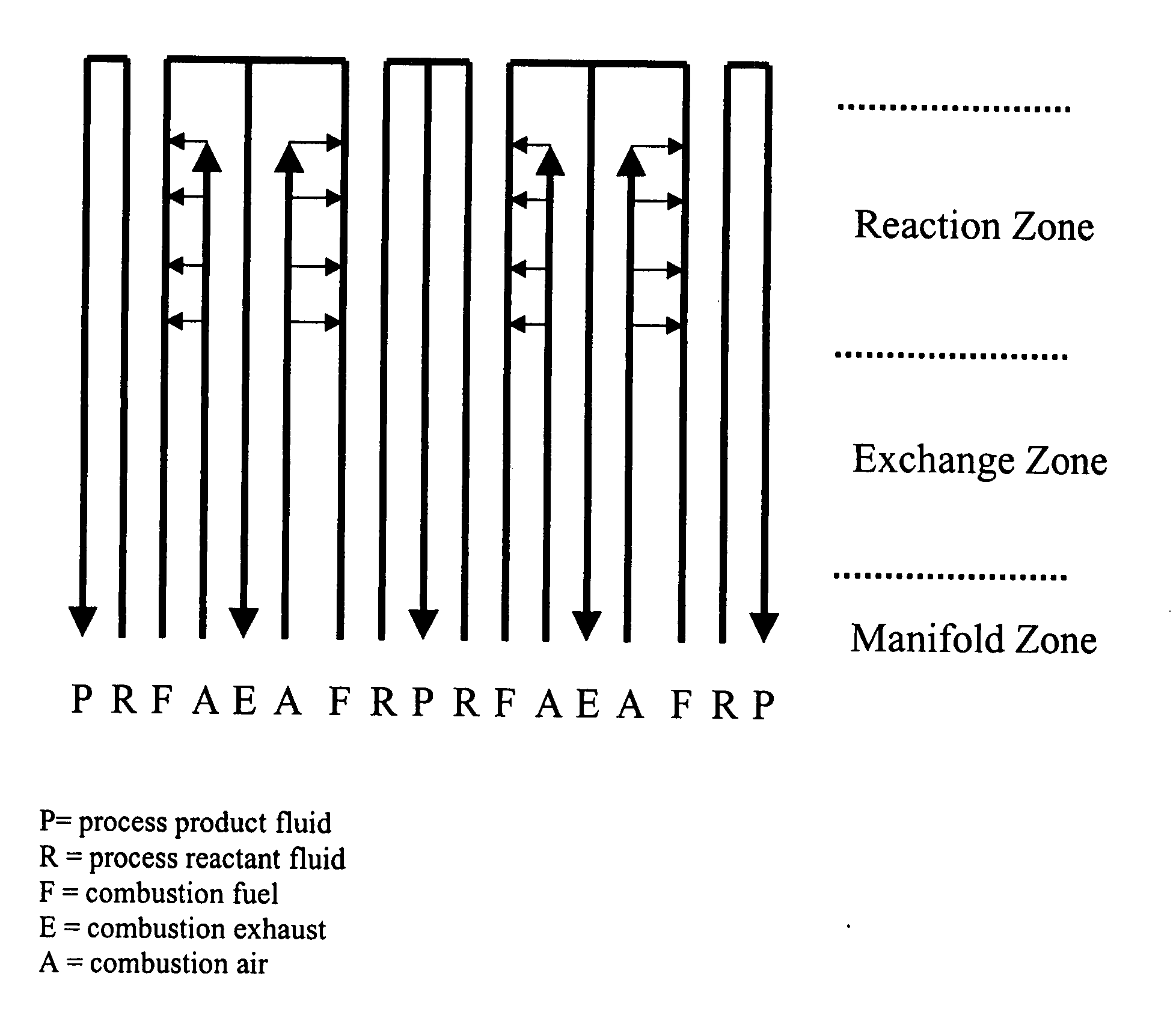
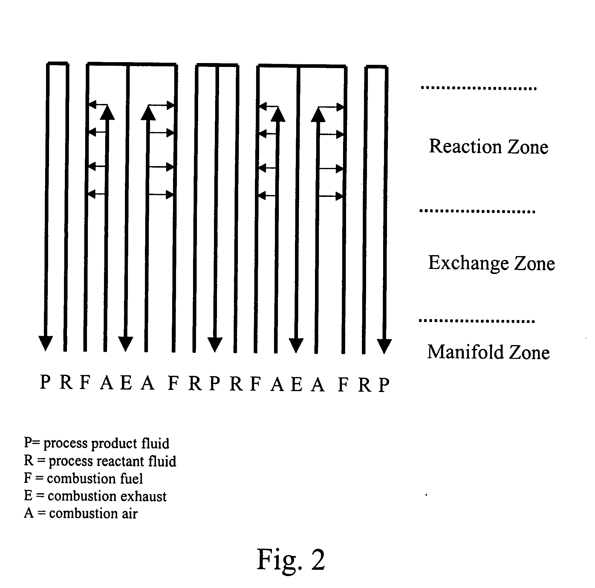
[0303] The microchannel ICR reactor system in these examples had the two-stream loop design described in the above section entitled Description of Preferred Embodiments. The streams entering the device may either be at ambient conditions or at a slightly elevated temperature. A series of microchannel exchangers were optionally used to provide additional preheat to the streams.

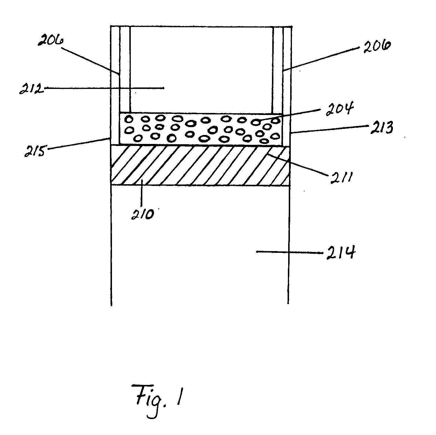
[0304] A multi-channel bonded ICR device was designed, fabricated, and operated for over 300 hours. This device was formed from stacking metal plates of various thicknesses (0.25, 0.36, 0.41, 0.51, 0.64, and 6.4 mm) with various portions cut away to form channels for flow of the several fluid streams and diffusion bonding the stack together, with thicker plates placed in the outermost edges of the stack of plates (like bookends). The device included 3 exothermic reaction (combustion) repeating units flanked by endothermic reaction (SMR) channels.

[0305] The process side of this diffu...

example 2 bonded

Device

Results and Discussion

[0344] The bonded ICR device of Example 2 was demonstrated using methane and steam at 2.5:1 steam:C, 850 C and 12.5 atm. Testing included 88 hours at 6 ms followed by >300 hours at 9 ms. Combustion fuel composition was 5-10% CH4, 0-2% CO, 6% CO2, and the balance H2. Excess combustion air was maintained between 3 and 7%.

[0345] Results of the testing are shown in Table 2 and FIGS. 28-31. In Table 2, average reactor temperatures were assumed to be the average of the three skin temperature measurements closest to the U-turn on one face, spanning the last quarter of the reaction zone. Skin temperatures reported in Table 2 were measured along the centerline of one face, tracking the edge nearest the middle combustion exhaust channel. FIG. 28 shows the SMR performance over the entire 400 hours of operation. In FIG. 29, combustion results are shown from the bonded ICR testing. One surprising result shown in FIG. 29 is combustion CH4 conversions which exceed the...


PUM

PropertyMeasurementUnit
lengthaaaaaaaaaa
heightaaaaaaaaaa
temperaturesaaaaaaaaaa

Abstract

Integrated Combustion Reactors (ICRs) and methods of making ICRs are described in which combustion chambers (or channels) are in direct thermal contact to reaction chambers for an endothermic reaction. Particular reactor designs are also described. Processes of conducting reactions in integrated combustion reactors are described and results presented. Some of these processes are characterized by unexpected and superior results, and / or results that can not be achieved with any prior art devices.

Description

RELATED APPLICATIONS [0001] This application is a divisional of U.S. patent application Ser. No. 10 / 222,196, filed Aug. 15, 2002, now U.S. patent Ser. No. ______. OTHER APPLICATIONS [0002] The invention may be further understood by reference to U.S. patent application Ser. No. 10 / 220,604 (Title: Multistream Microchannel Device; Attorney Docket No. 02-001), and U.S. Pat. Nos. 6,622,519 and 6,969,505, all of which are incorporated herein by reference.INTRODUCTION [0003] Currently, endothermic reactions performed in microreactors are driven using heat from an external source, such as the effluent from an external combustor. In doing so, the temperature of the gas stream providing the heat is limited by constraints imposed by the materials of construction. For example, a typical microreactor constructed from Inconel 625 might be limited in use for gas service to temperatures of ˜1050° C. or less. Practically, this means that the effluent from an external combustor must be diluted with c...

Claims


Application Information

Patent Timeline
Patent Type & Authority Applications(United States)
IPC IPC(8): B01J19/00B29C65/02C01B3/38F23C13/00F23C99/00F28D9/00
CPCB01J19/0093Y10T156/10B01J2219/00164B01J2219/00783B01J2219/0081B01J2219/00835B01J2219/00873B01J2219/00984C01B3/382C01B3/384C01B2203/0233C01B2203/0811C01B2203/0822C01B2203/142F23C13/00F23C99/006F23C2900/03001F23C2900/03002F28D9/0093F28F2260/02B01J2219/00117Y02P20/52Y02P20/10
Inventor TONKOVICH, ANNA LEEROBERTS, GARYFITZGERALD, SEAN P.NEAGLE, PAUL W.QIU, DONGMINGSCHMIDT, MATTHEW B.PERRY, STEVEN T.HESSE, DAVID J.LUZENSKI, ROBERT J.CHADWELL, G. BRADLEYPENG, YINGMATHIAS, JAMES A.GANO, NATHAN P.LONG, RICHARD Q.ROGERS, WM. ALLENARORA, RAVISIMMONS, WAYNE W.YANG, BARRY L.KUHLMANN, DAVID J.WANG, YONGYUSCHAK, THOMAS D.FORTE, THOMASMONAHAN, JOHN ARTHURJETTER, ROBERT
Owner VELOCYS INC
Why Eureka
Try Eureka