Heat sink having directive heat elements

a technology of heat sinks and heat elements, which is applied in the direction of cooling/ventilation/heating modifications, semiconductor devices, semiconductor/solid-state device details, etc., can solve the problems of limiting the amount of power, generating a substantial amount of heat, and limiting the efficiency of heat transfer from the heat generating device (i.e. the led device), so as to reduce the amount of heat generated, and reduce the effect of heat generation

Inactive Publication Date: 2006-08-17
LARSON RALPH I
View PDF8 Cites 20 Cited by
  • Summary
  • Abstract
  • Description
  • Claims
  • Application Information

AI Technical Summary

Benefits of technology

[0009] With this particular arrangement, a heat sink which transforms a high heat flux density which exists at one end of the directive heat elements proximate a device being cooled to a low heat flux density at an opposite end of the directive heat elements is provided. By closely spacing the end of the directive heat elements proximate the heat generating device and increasing the spacing of the opposite ends the directive heat elements, the heat sink transfers heat from a relatively small area (i.e. the area proximate the heat generating device) of the heat sink to a relatively large area of the heat sink (i.e. an area of the heat sink distal from the heat generating device). By positioning the directive heat elements in

Problems solved by technology

Such LEDs can generate between 1-6 watts (W) of energy and consequently generate a substantial amount of heat.
One problem with this approach is that the junctions between the LED device and the heat sink impede the efficient transfer of heat from the heat genera

Method used


Image

  • Heat sink having directive heat elements
  • Heat sink having directive heat elements
  • Heat sink having directive heat elements

Examples


Embodiment Construction

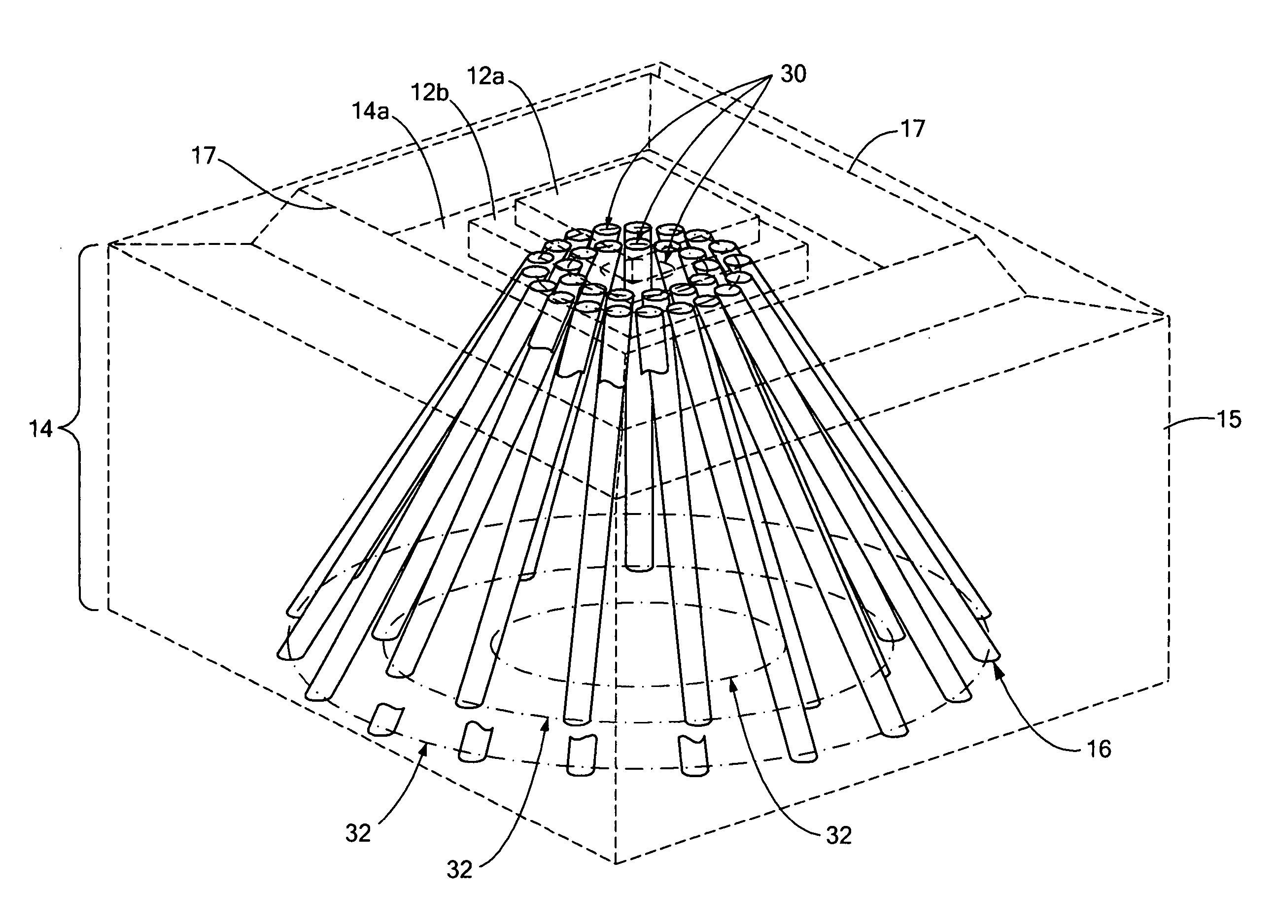
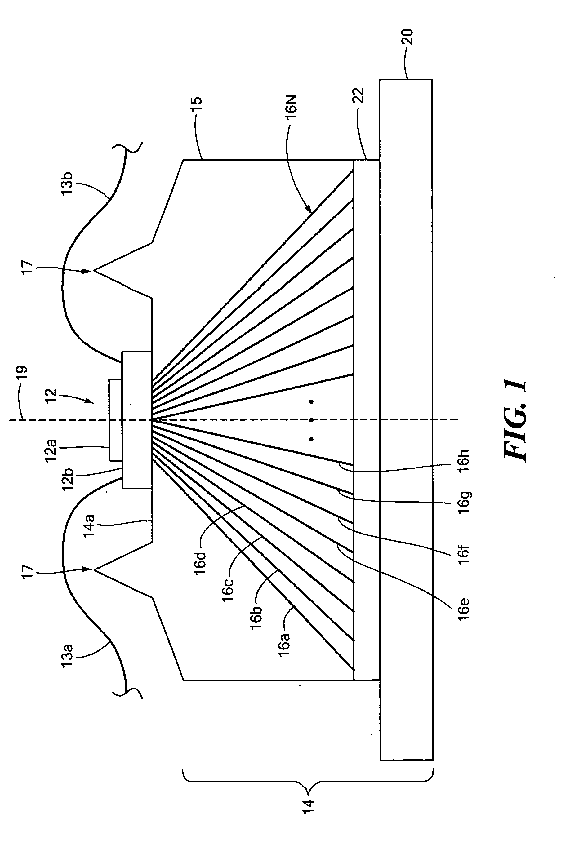
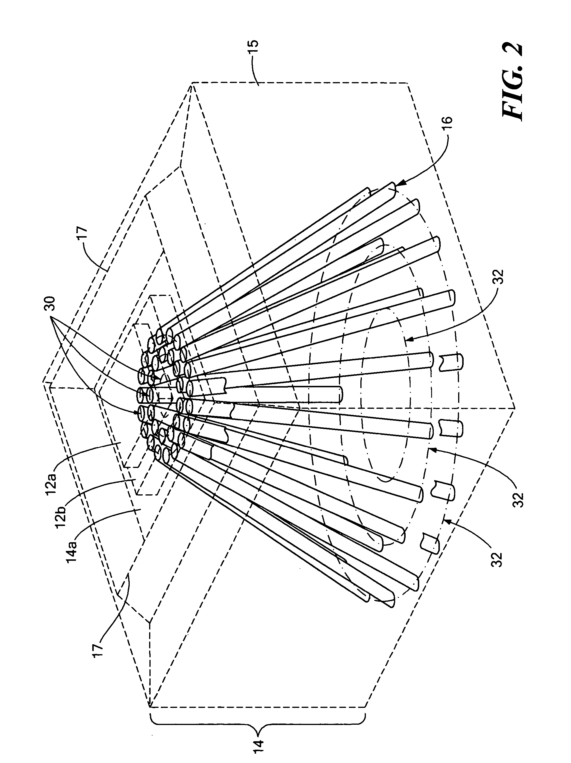
[0012] Referring now to FIGS. 1 and 2 in which like elements are provided having like reference designations, a heat generating device 12, is disposed on a first surface 14a of a heat sink 14 provided from a heat conducting substrate 15 (also referred to herein as a matrix 15) having a plurality of directive heat elements 16 (also referred to herein as heat pipes, fibers, strands or bundles) disposed therein. In this particular embodiment, the heat generating device 12 is shown as two stacked semiconductors 12a, 12b which can form an LED disposed in a recess region (more clearly visible in FIG. 2) defined by walls 17 projecting from a surface of the substrate 15.

[0013] The heat generating device 12 may be thermally coupled to the heatsink 14 via a solder connection (e.g. a semiconductor die soldered to the heat sink 14), epoxy or via any other connection technique or mechanism now known or unknown to those of ordinaru skill in the art. Electrical signal paths 13a, 13b may be used t...


PUM


Abstract

A heat sink includes a heat conducting substrate and a plurality of directive heat elements disposed within the substrate such that a first end of each of the plurality directive heat elements are adapted to be disposed proximate a heat generating device and a second end of each of the plurality of directive heat elements are spaced apart within the substrate to promote the transfer to heat from the heat generating device through the directive elements to an area of the heat conducting substrate which is larger than the area of the heat generating device. In this way, the heat sink transforms a high heat flux density existing at one end of the directive heat elements proximate a device being cooled to a low heat flux density at an opposite end of the directive heat elements.

Description

CROSS-REFERENCE TO RELATED APPLICATIONS [0001] This application claims the benefit of provisional application No. 60 / 652,383 filed on Feb. 11, 2005 under 35 U.S.C. §119(e) and is incorporated herein by reference in its entirety.STATEMENTS REGARDING FEDERALLY SPONSORED RESEARCH [0002] Not applicable. FIELD OF THE INVENTION [0003] This invention relates generally to heat sinks and more particularly heat sinks having directive heat elements. BACKGROUND OF THE INVENTION [0004] As is known in the art, certain classes of light emitting diodes (LEDs) are often provided from Group III-IV semiconductor materials such as Gallium-Arsenide (GaAs). Such LEDs can generate between 1-6 watts (W) of energy and consequently generate a substantial amount of heat. Thus, the LEDs are disposed on a heat sink. [0005] Heat sinks are generally provided from thermally conductive materials such as copper (Cu) or aluminum (Al). Copper has a coefficient of thermal expansion which is relatively large compared wi...

Claims


Application Information

Patent Timeline
IPC IPC(8): H05K7/20
CPCH01L23/3677H01L23/373H01L23/427H01L2224/48091H01L2924/00014
Inventor LARSON, RALPH I.
Owner LARSON RALPH I
Why Eureka
Try Eureka