Systems and methods for utilizing an array of power storage devices, such as batteries

a power storage device and array technology, applied in parallel/serial switching, instruments, transportation and packaging, etc., can solve the problem of no main recycling infrastructure in the world that treats only automotive li-ion batteries

Active Publication Date: 2017-12-05
GOGORO
View PDF370 Cites 3 Cited by
  • Summary
  • Abstract
  • Description
  • Claims
  • Application Information

AI Technical Summary

Benefits of technology

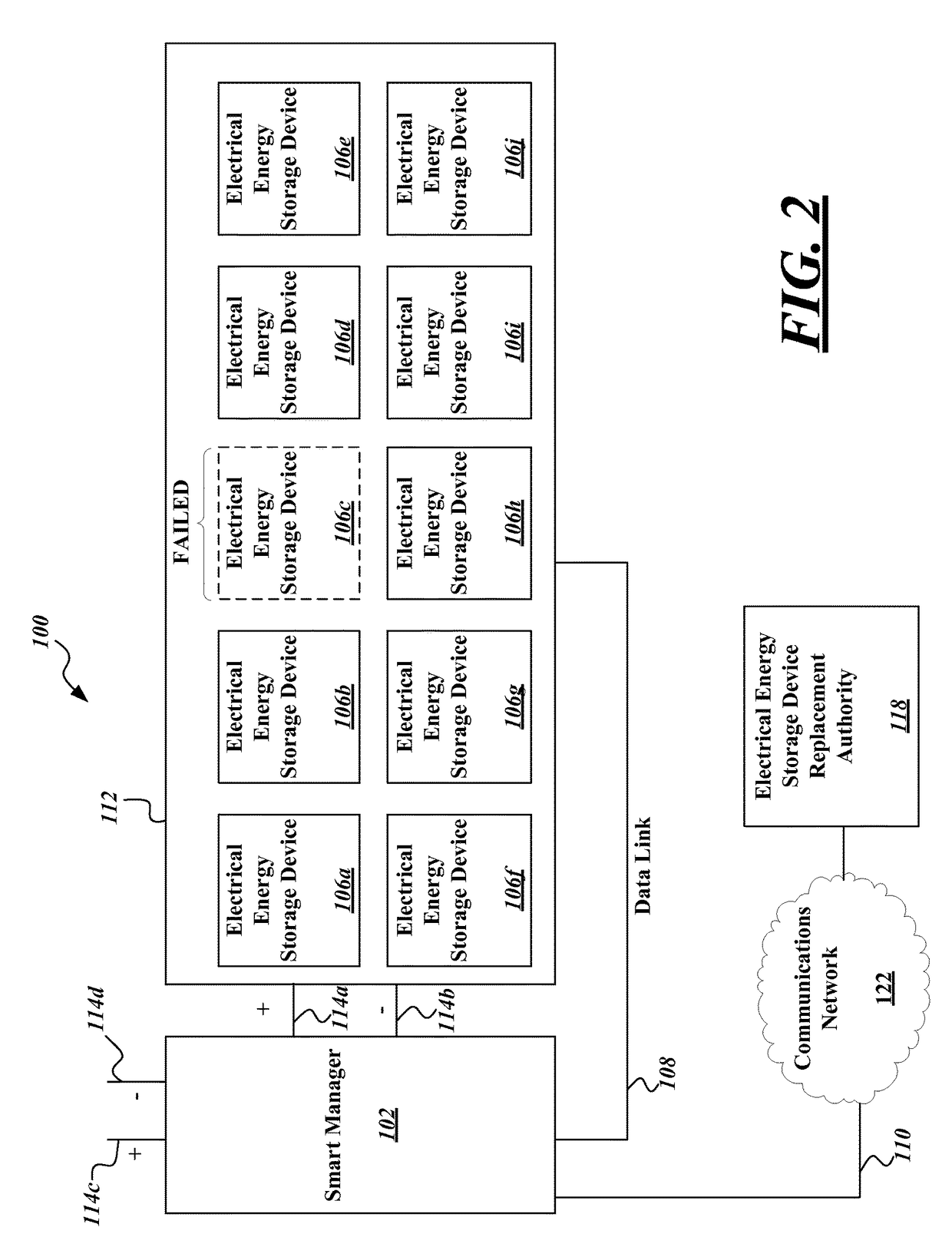
[0007]The system wherein the at least one controller may be further configured to: prevent power to be drawn from the electrical energy storage device determined to be faulty by being configured to disconnect the electrical energy storage device determined to be faulty from an electrical circuit to which others of the plurality of electrical energy storage devices are connected in the array.
[0014]A method in a system for utilizing an array of electrical energy storage devices may be summarized as including receiving, by a communications module of the system for utilizing an array of electrical energy storage devices, information regarding status of each of a plurality of electrical energy storage devices of the array of electrical energy storage devices; determining, by a controller of the system for utilizing an array of electrical energy storage devices, regarding from which of the plurality of electrical energy storage devices to allow power to be drawn and when to allow power to be drawn from particular electrical energy storage devices of the plurality of electrical energy storage devices, based on the received information regarding status of each of the plurality of electrical energy storage devices; and causing, by the controller of the system for utilizing an array of electrical energy storage devices, power to be drawn from the particular electrical energy storage devices of the plurality of electrical energy storage devices according to the determination. The determining may include determining that an electrical energy storage device of the plurality of electrical energy storage devices is faulty based on the received information regarding status of each of the plurality of electrical energy storage devices; and in response to the determination that the electrical energy storage device is faulty, preventing power from being drawn from the electrical energy storage device determined to be faulty.

Problems solved by technology

However, after rechargeable electrical energy storage devices used in transportation applications no longer have the required capacity to continue to be used in such transportation applications, other uses of these electrical energy storage devices may need to be found in order to utilize the remaining capacity.
In particular, with lithium recycling in its infancy, there is currently no main recycling infrastructure in the world that treats only automotive Li-ion batteries.

Method used


Image

  • Systems and methods for utilizing an array of power storage devices, such as batteries
  • Systems and methods for utilizing an array of power storage devices, such as batteries
  • Systems and methods for utilizing an array of power storage devices, such as batteries

Examples


Embodiment Construction

[0030]In the following description, certain specific details are set forth in order to provide a thorough understanding of various disclosed embodiments. However, one skilled in the relevant art will recognize that embodiments may be practiced without one or more of these specific details, or with other methods, components, materials, etc. In other instances, well-known structures associated with batteries, supercapacitors or ultracapacitors, power converters including but not limited to transformers, rectifiers, DC / DC power converters, switch mode power converters, controllers, and communications systems and structures and networks have not been shown or described in detail to avoid unnecessarily obscuring descriptions of the embodiments.

[0031]Unless the context requires otherwise, throughout the specification and claims which follow, the word “comprise” and variations thereof, such as “comprises” and “comprising,” are to be construed in an open, inclusive sense that is as “includi...


PUM


Abstract

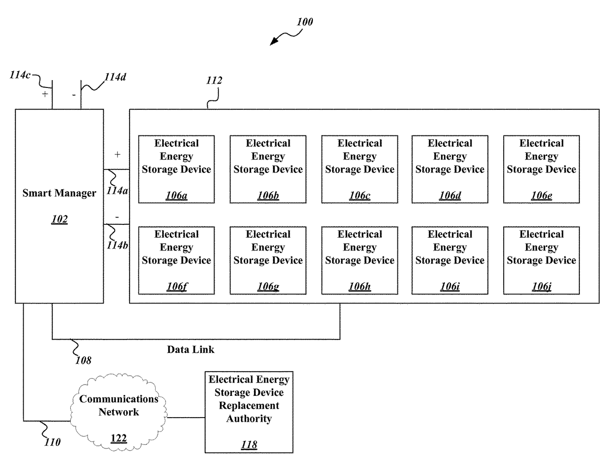
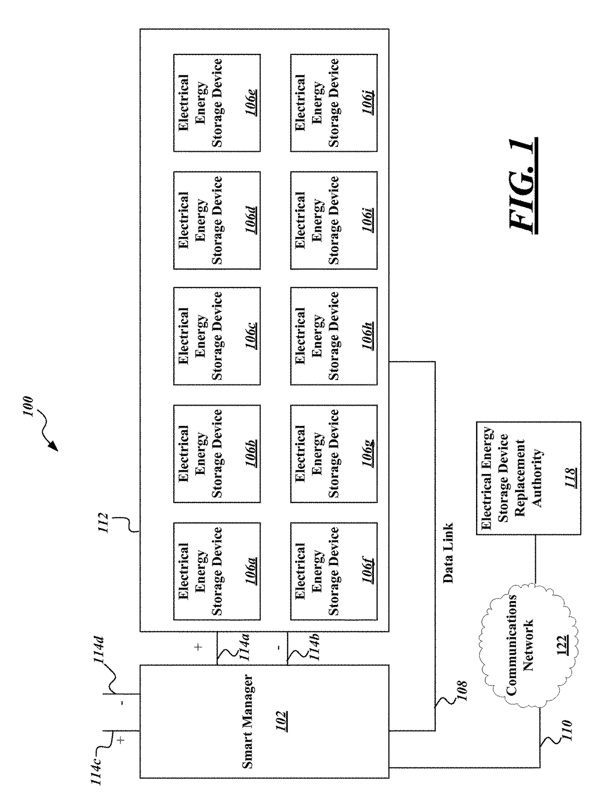
A system for utilizing an array of electrical energy storage devices utilizes a smart manager that categorizes electrical energy storage devices in the array based on electrical energy storage device age and / or internal resistance level and causes those electrical energy storage devices with similar ages and / or resistance levels to be concurrently depleted. This is followed by concurrently depleting the electrical energy storage devices in a different category. The system also disconnects faulty electrical energy storage devices in the array and helps alleviate the need to carefully consider and reconfigure the location of individual electrical energy storage devices in the array. The system facilitates forecasting actual capacity and thus helps to guarantee available capacity and to actively maintain capacity via maintenance crews that need simply remove and replace cells as advised by the smart manager. The system 100 facilitates permitting a quality of service (QoS) to be provided to mission critical entities (banks, hospitals, etc.).

Description

BACKGROUND[0001]Technical Field[0002]The present disclosure generally relates to the charging and energy release from rechargeable electrical energy storage devices (e.g., secondary batteries, supercapacitors or ultracapacitors), which may be suitable for use in a variety of fields or applications, for instance transportation and non-transportation uses.[0003]Description of the Related Art[0004]There are a wide variety of uses or applications for electrical energy storage devices. One such application is in the field of transportation. However, after rechargeable electrical energy storage devices used in transportation applications no longer have the required capacity to continue to be used in such transportation applications, other uses of these electrical energy storage devices may need to be found in order to utilize the remaining capacity. Thus a need exists to utilize these aged electrical energy storage devices efficiently and in a more cost-effective manner.[0005]Additionally...

Claims


Application Information

Patent Timeline
Patent Type & Authority Patents(United States)
IPC IPC(8): H02J7/00H02J7/34
CPCH02J7/0063H02J2007/0067H02J7/345H02J7/0024G01R31/392H02J7/0025
Inventor TAYLOR, MATTHEW WHITINGLUKE, HOK-SUM HORACE
Owner GOGORO
Why Eureka
Try Eureka