

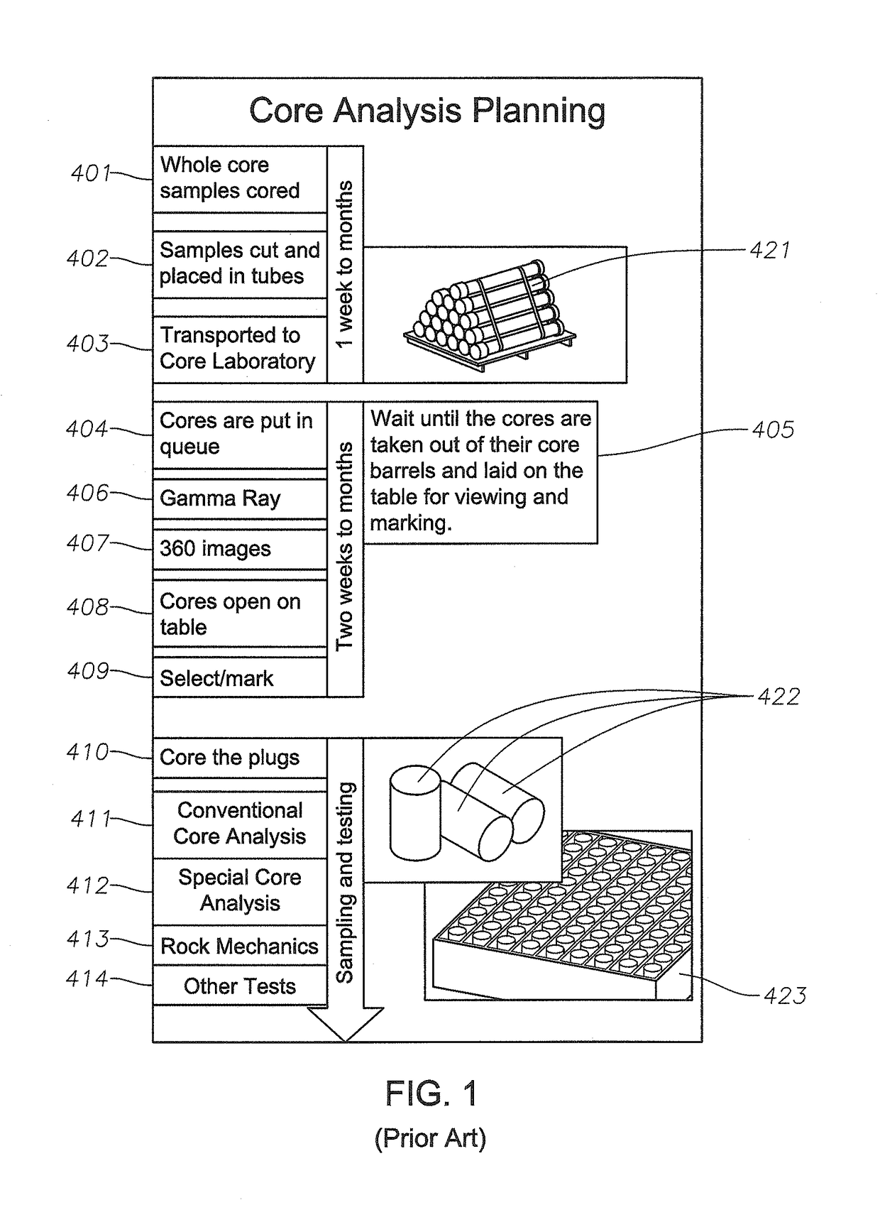
Cored rock analysis planning through CT images
a technology of cored rock and analysis planning, applied in the direction of image enhancement, material analysis using wave/particle radiation, instruments, etc., can solve the problems of reducing the and reducing the number of cored rock samples. , to achieve the effect of enhancing efficiency, cost and time saving, and increasing the speed and accuracy of core analysis planning
- Summary
- Abstract
- Description
- Claims
- Application Information
AI Technical Summary
Benefits of technology
Problems solved by technology
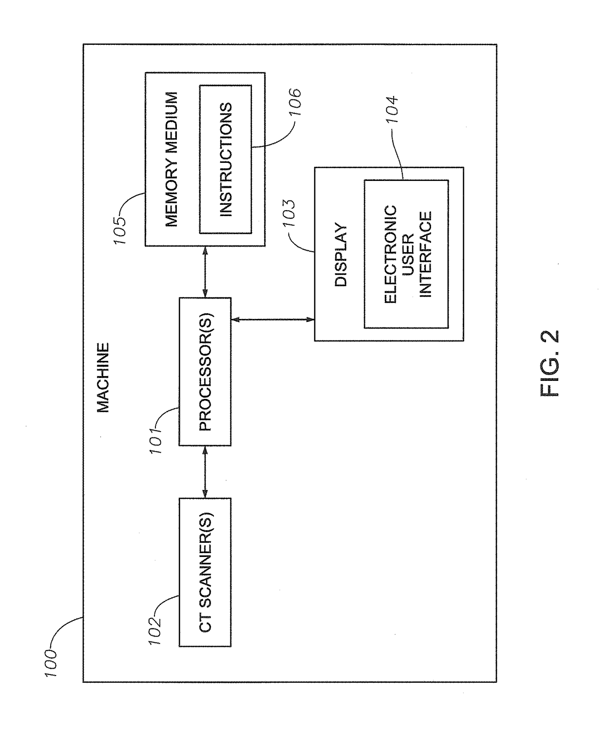
Method used
Image


Examples
Embodiment Construction
[0048]So that the manner in which the features and advantages of the embodiments of methods, machines, systems, and non-transitory computer-readable medium having computer program stored therein of the present disclosure, as well as others, which will become apparent, may be understood in more detail, a more particular description of the embodiments of methods, machines, systems, and non-transitory computer-readable medium having computer program stored therein of the present disclosure briefly summarized supra may be had by reference to the embodiments thereof, which are illustrated in the appended drawings, which form a part of this specification. It is to be noted, however, that the drawings illustrate only various embodiments of the embodiments of methods, machines, systems, and non-transitory computer-readable medium having computer program stored therein of the present disclosure and are therefore not to be considered limiting of the embodiments of methods, machines, systems, ...
PUM
| Property | Measurement | Unit |
|---|---|---|
| length | aaaaa | aaaaa |
| length | aaaaa | aaaaa |
| structure | aaaaa | aaaaa |
Abstract
Description
Claims
Application Information