
System and method for managing AC power using auxiliary DC-to-AC inversion

a technology of auxiliary dc and ac, applied in the direction of ac network voltage adjustment, information technology support system, climate sustainability, etc., can solve the problems of wasting dc energy supplied, power inverter may spend a significant amount of time at low efficiency power setting, and low efficiency at high power setting, etc., to achieve excellent power inverter efficiency and accurate control of peak demand.

Inactive Publication Date: 2017-12-19
NANTENERGY INC
View PDF10 Cites 0 Cited by
  • Summary
  • Abstract
  • Description
  • Claims
  • Application Information

AI Technical Summary

Benefits of technology

The patent is about a power converter that makes efficient use of battery capacity and is controlled to manage the demand for power from an electric utility. It uses a duty cycle schedule to achieve efficient power conversion and meets the target demand level, avoiding inefficient use of battery capacity. This results in a conserved battery capacity and better tracking of the target demand level, reducing the impact of system control jitter.

Problems solved by technology

DC-to-AC power converters or inverters tend to have an efficiency curve that peaks at an optimum power output level, with a relatively low efficiency at high power settings.
Thus, the power inverter may spend a significant amount of time at low efficiency power settings.
This results in a waste of DC energy that is being supplied to hold down the AC electric demand.
When the source of DC energy is a battery, this inefficiency results in a waste of limited battery capacity.
Since the instantaneous demand can vary significantly, the actual peak demand of a continuously rolling 15-minute period may occur in between the power company's measurement times. If the peak demand happens to occur during the measurement time, the client's billing rate is adversely affected.

Method used


Image

  • System and method for managing AC power using auxiliary DC-to-AC inversion
  • System and method for managing AC power using auxiliary DC-to-AC inversion
  • System and method for managing AC power using auxiliary DC-to-AC inversion

Examples


Embodiment Construction

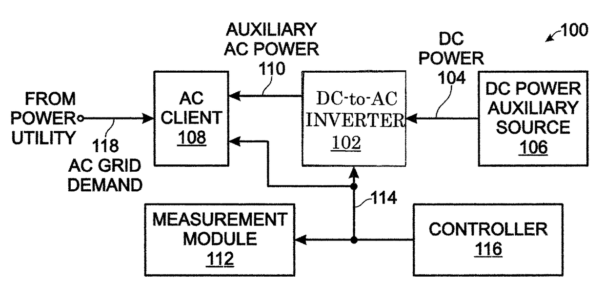
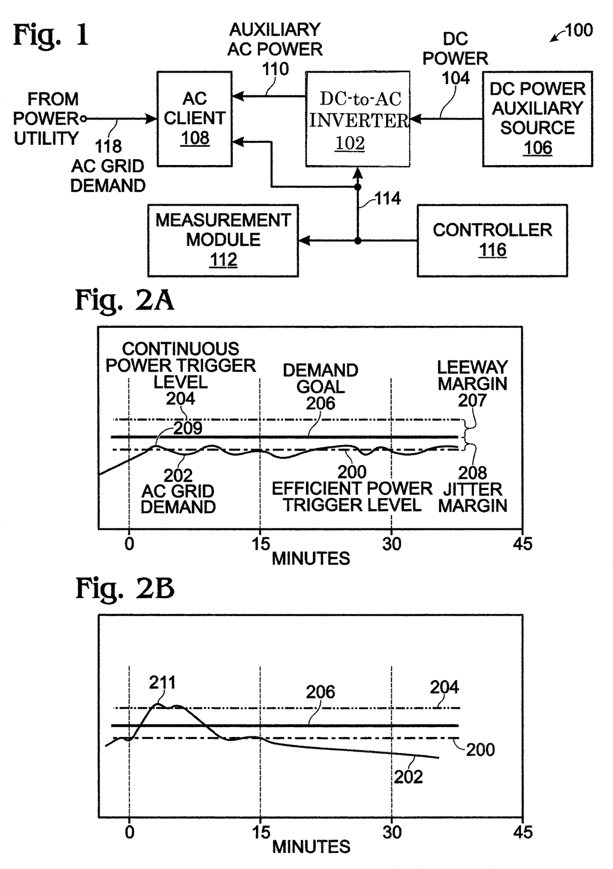
[0020]FIG. 1 is a schematic block diagram representing a system for managing demand for an alternating current (AC) client using direct current (DC)-to-AC power inversion as an auxiliary source of power. The system 100 comprises a DC-to-AC inverter 102 having an input on line 104 connected to a DC power auxiliary source 106. A battery is one example of a DC power auxiliary source. The inverter 102 has selectable inversion power output levels connected to an AC client 108 on line 110 to supply auxiliary power for a portion of a fluctuating AC grid demand of the client. The AC grid demand is monitored on line 118.

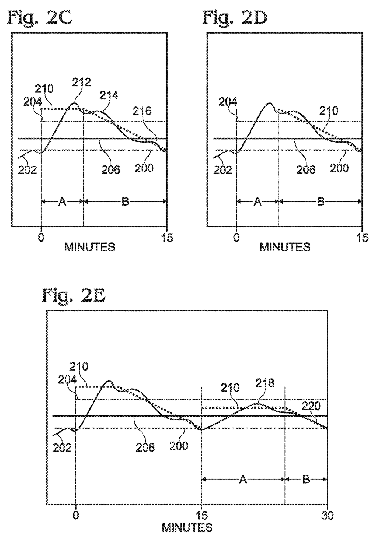
[0021]A measurement module 112 has an interface connected to the DC-to-AC inverter on line 114. The measurement module 112 averages the AC grid demand supplied on line 118. In each of a series of periodic time intervals, the measurement module 112 compares a current AC grid demand average in a current time interval to a demand goal. More explicitly, the current AC grid demand...


PUM


Abstract

A system and method are provided for managing demand for a client with a fluctuating AC power grid demand, using DC-to-AC power inversion as an auxiliary source of power. The inverter has a selectable inversion power output levels connected to the AC client to supply auxiliary power for a portion of the AC power demand. The AC grid demand is averaged. In each of a series of periodic time intervals, a current AC grid demand average in a current time interval is compared to a demand goal, which is the highest AC grid demand average, as measured at an end of a time interval, and selected from a plurality of time intervals. The inverter output power level is selected so that the current AC grid demand average is less than or equal to the demand goal by the end of the current time interval.

Description

BACKGROUND OF THE INVENTION[0001]1. Field of the Invention[0002]This invention generally relates to direct current (DC)-to-alternating current (AC) power inversion and, more particularly, to a system and method for efficiently managing to use of DC-to-AC power inversion for a client using metered AC power from a utility.[0003]2. Description of the Related Art[0004]DC-to-AC power converters or inverters tend to have an efficiency curve that peaks at an optimum power output level, with a relatively low efficiency at high power settings. Typical load-following peak management systems track the load when it is above a target demand level. Thus, the power inverter may spend a significant amount of time at low efficiency power settings. This results in a waste of DC energy that is being supplied to hold down the AC electric demand. When the source of DC energy is a battery, this inefficiency results in a waste of limited battery capacity.[0005]Electric peak demand systems that track the A...

Claims


Application Information

Patent Timeline
Patent Type & Authority Patents(United States)
IPC IPC(8): H02J3/06H02J3/38H02J3/14
CPCH02J3/381H02J3/14Y04S20/222Y02B70/3225H02J2310/12
Inventor PARK, DANIEL
Owner NANTENERGY INC
Learn More