
Satellite communication system, LEO satellite relaying communications between a GEO satellite and terrestrial stations, the uplinks and downlinks using the same frequency band and time-division multiplexing

a satellite communication and satellite technology, applied in the field of long-range data transmission systems, can solve the problems of limited earth coverage, limited coverage of the system using low-orbit satellites, and limited coverage of the network of ground stations in the system, and achieve good levels of performance (link budget, availability)

Active Publication Date: 2017-12-19
AIRBUS DEFENCE & SPACE
View PDF21 Cites 2 Cited by
  • Summary
  • Abstract
  • Description
  • Claims
  • Application Information

AI Technical Summary

Benefits of technology

This solution provides continuous coverage and reduces latency, enabling efficient bidirectional data communication even in areas with limited satellite visibility, while simplifying system design and reducing costs by sharing onboard power and frequency bands.

Problems solved by technology

However, the coverage provided by the network of ground stations in the systems using low orbit satellites, such as Orbcomm and Argos, is limited by the deployment of ground stations (GES) and the existing systems provide only limited coverage of Earth in this mode.
With this method of operation, the communication delays are long and make bidirectional communications difficult under acceptable conditions, given that the delays are typically between a few minutes and the 100 to 150 minutes of duration of a complete orbit of the LEO satellite.
It is clear that current hybrid systems exhibit a high level of complexity, synonymous with increased cost for setup and use.

Method used


Image

  • Satellite communication system, LEO satellite relaying communications between a GEO satellite and terrestrial stations, the uplinks and downlinks using the same frequency band and time-division multiplexing
  • Satellite communication system, LEO satellite relaying communications between a GEO satellite and terrestrial stations, the uplinks and downlinks using the same frequency band and time-division multiplexing
  • Satellite communication system, LEO satellite relaying communications between a GEO satellite and terrestrial stations, the uplinks and downlinks using the same frequency band and time-division multiplexing

Examples


Embodiment Construction

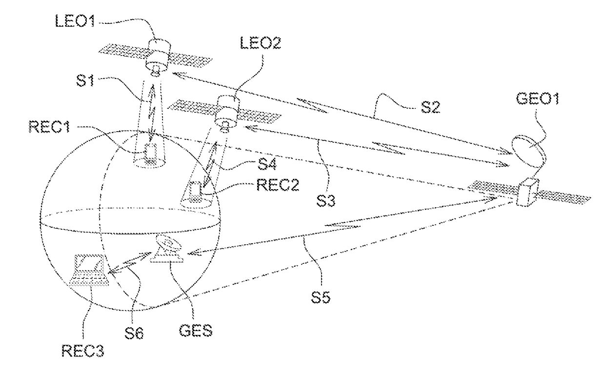
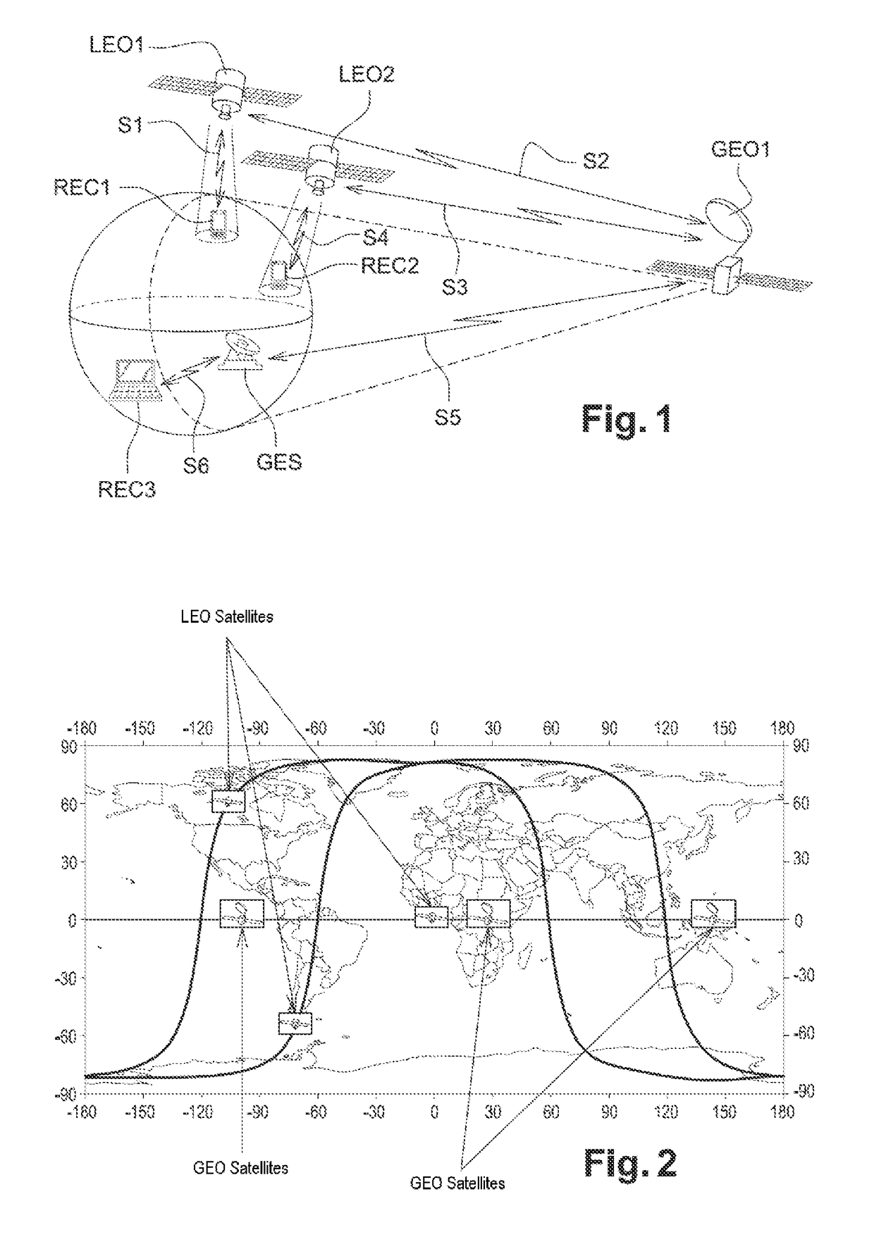
[0079]The architecture of a telecommunication system according to the invention is illustrated by FIGS. 1 and 2. As can be seen in these figures, the system proposed uses two satellite constellations.

[0080]The first constellation is made up of one or more stationary satellites (likewise called GEO in the remainder of the description).

[0081]In the present case, the system described here by way of non-limiting example is based on a constellation of three stationary satellites GEO1, GEO2, GEO3 that have been put into geostationary orbit above the three main continental areas (for example at longitudes 265° E, 25° E, 145° E, respectively, as illustrated in FIG. 2). The stationary satellites GEO1, GEO2, GEO3 operate in the band called MSS L (1.5 / 1.7 GHz).

[0082]The constellation of the stationary satellites GEO1, GEO2, GEO3 is controlled by one or more terrestrial control stations, arranged in sight of the stationary satellites GEO1, GEO2, GEO3 that they control, which perform the control...


PUM


Abstract

A payload for a repeater satellite of a communication system. The repeater satellite being placed into drift orbit above the surface of a celestial body. The payload being configured to repeat data received from a stationary satellite above the surface of the celestial body towards a terminal substantially at the surface of the celestial body, and to repeat data received from the terminal towards the stationary satellite. The payload is further configured to use a single frequency band for repeating data towards the stationary satellite, referred to as uplink transmission, and for repeating data towards the terminal, referred to as downlink transmission, as well as to time-division multiplex the uplink transmissions and the downlink transmissions. Also, a telecommunication system includes a repeater satellite provided with aforesaid payload, and a satellite communication method for transferring data between the terminal and the stationary satellite.

Description

RELATED APPLICATIONS[0001]This application is a §371 application from PCT / EP2012 / 060359 filed Jun. 1, 2012, which claims priority from French Patent Application No. 1101850 filed Jun. 16, 2011, each of which is herein incorporated by reference in its entirety.FIELD OF THE INVENTION[0002]The invention pertains to the field of long-range data transmission systems. It relates more particularly to systems and methods for data communication (data transfer, remote control, terminal tracking . . . ) between users equipped with small mobile terminals.CONTEXT OF THE INVENTION AND PROBLEM POSED[0003]The question of long-range data transmission from or to a mobile terminal is posed particularly for connections between computers (“machine to machine” or M2M). This area of transmission is then characterized by a distinctly lower data rate need than for connections of image or internet type, and / or by the ability to use an intermittent rather than continuous connection.[0004]A first approach to t...

Claims


Application Information

Patent Timeline
Patent Type & Authority Patents(United States)
IPC IPC(8): H04B7/212H04B7/185H04B7/195
CPCH04B7/18513H04B7/195H04B7/18515
Inventor TRONC, JEROMEDUNAT, JEAN-CHRISTOPHE
Owner AIRBUS DEFENCE & SPACE
Learn More