
Optic module cage assembly utilizing a stationary heatsink

Active Publication Date: 2017-12-26
CIENA
View PDF2 Cites 7 Cited by
  • Summary
  • Abstract
  • Description
  • Claims
  • Application Information

AI Technical Summary

Benefits of technology

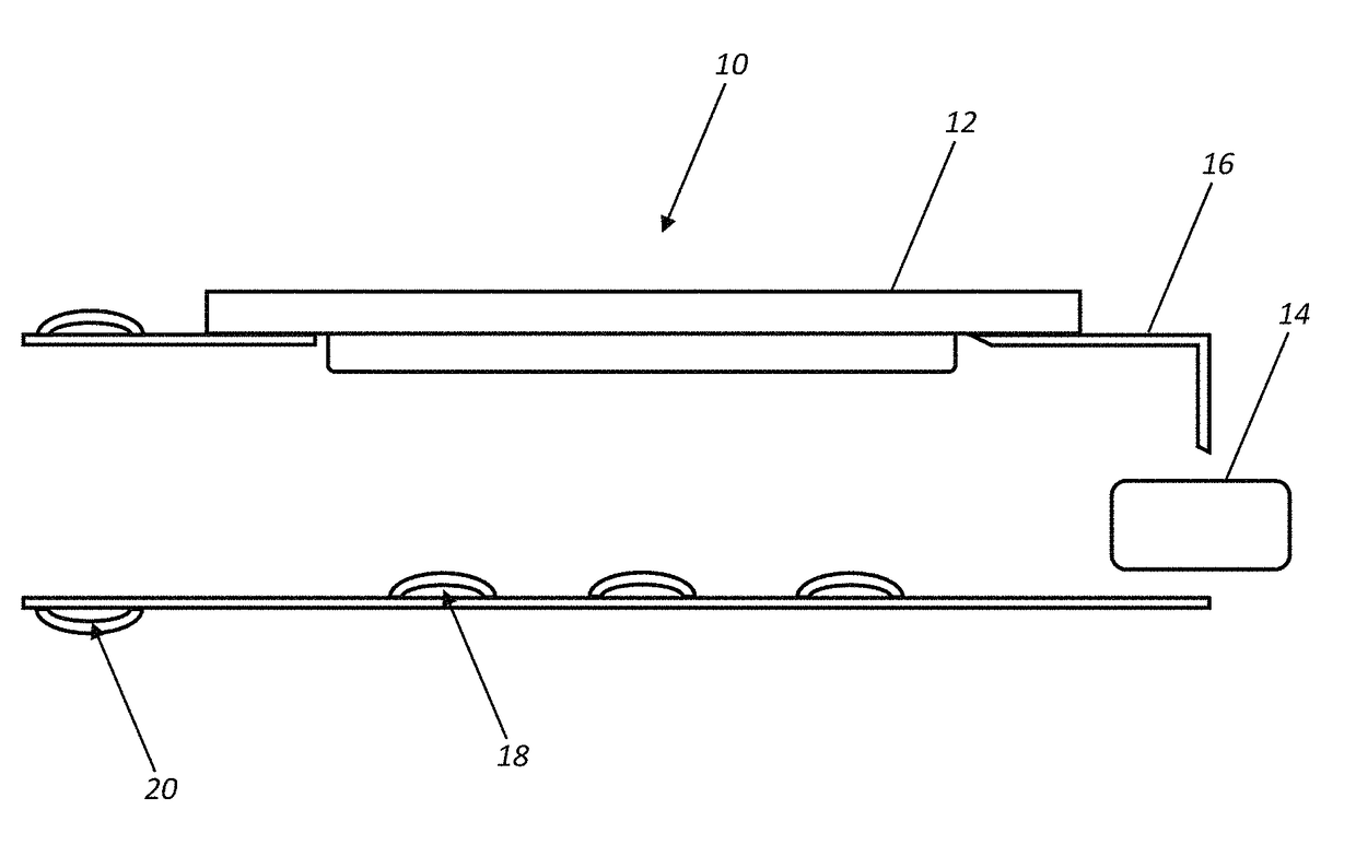
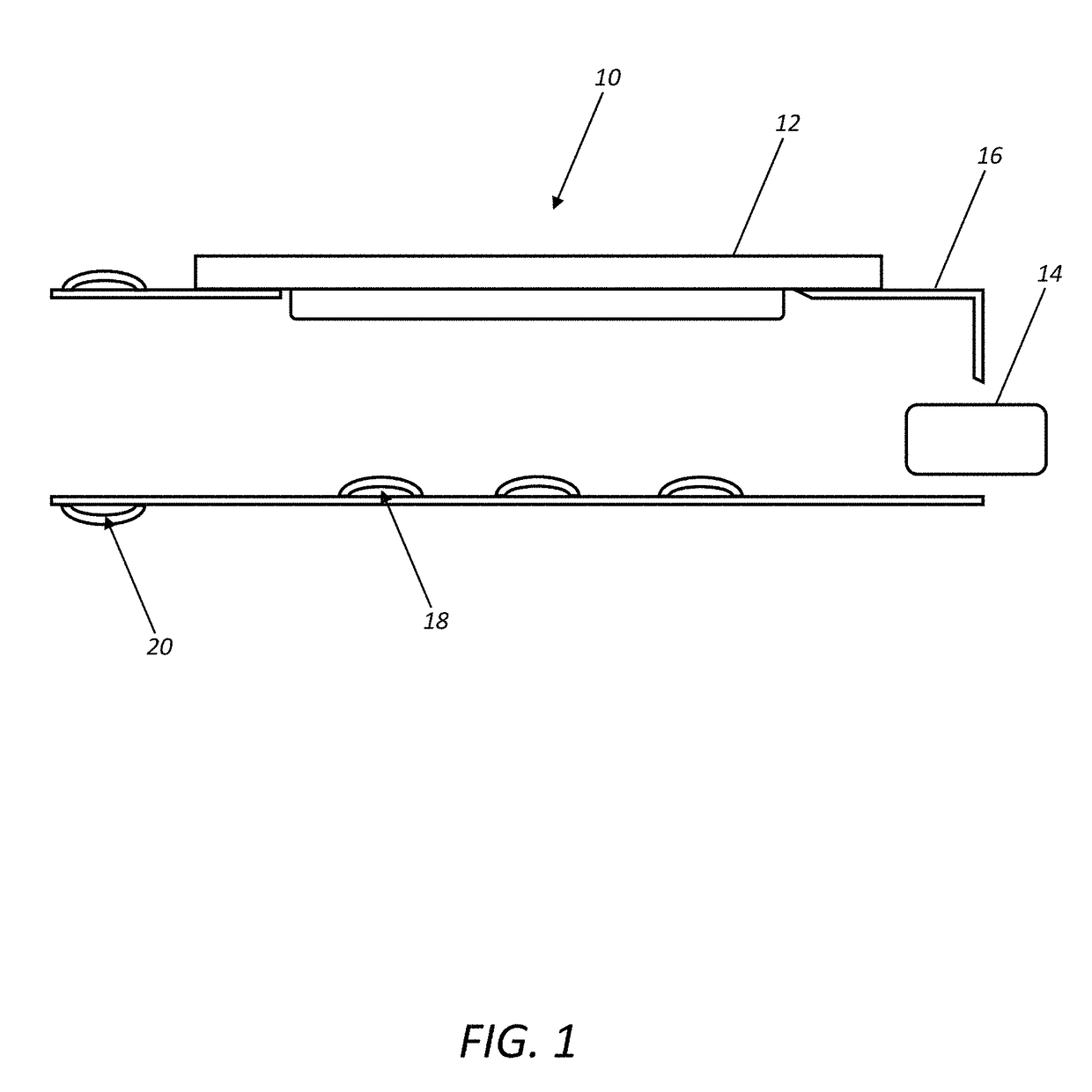
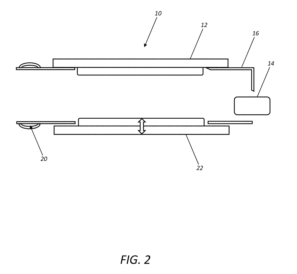
The present invention provides an optic module cage assembly that uses a stationary heatsink and multiple optic module cages that use the same heatsink. This configuration decreases the complexity of the optical system and provides better cooling. Each optic module is connected to the associated PCB using a floating connector that allows for movement of the optic module. The use of a common heatsink allows for a variety of shapes to be used, and can be coupled to a unified heat pipe, integrated fan, or thermoelectric cooler for even better cooling performance.

Problems solved by technology

The use of separate floating heatsinks necessarily limits the size of each, thereby limiting the cooling effectiveness of each.
This becomes problematic when, for example, the temperature maximum for each optic module is 70 degrees C. or the like, especially for a downstream optic module that is subjected to compounded heating from other upstream optic modules.
It simply becomes impossible to cool the optical system without utilizing more complex and expensive cooling systems.
The use of heat pipes is not practical, as each floating heatsink floats independently.

Method used


Image

  • Optic module cage assembly utilizing a stationary heatsink
  • Optic module cage assembly utilizing a stationary heatsink
  • Optic module cage assembly utilizing a stationary heatsink

Examples


Embodiment Construction

[0015]Again, in various exemplary embodiments, the present invention provides an optic module cage assembly that utilizes a stationary heatsink, and a plurality of optic module cages that utilize a common stationary heatsink. In other words, the optic module cage(s) is / are mounted to the (common) stationary heatsink, as opposed to the associated PCB(s), as is done conventionally. This decreases optical system complexity and provides superior optical system cooling characteristics. Each of the optic modules is electrically coupled to the associated PCB using a floating connector that accommodates a degree of movement of the optic module as it engages the stationary heatsink. The use of a common stationary heatsink to cool multiple optic modules allows a relatively large, and therefore very effective, heatsink having a variety of shapes to be used. This common stationary heatsink may readily be thermally coupled to a unified heat pipe, an integrated fan, and / or a thermoelectric cooler...


PUM


Abstract

An optic module cage assembly configured to selectively receive and retain an optic module, including: an optic module cage body configured to selectively receive and retain the optic module; a stationary heatsink fixedly attached to a side of the optic module cage body; one or more spring members disposed opposite the stationary heatsink and configured to bias the optic module towards the stationary heatsink; and a floating connector disposed partially within the optic module cage body and configured to make an electrical connection with the optic module, wherein the floating connector is configured to move in a constrained manner with respect to the optic module cage body. Optionally, the optic module cage assembly also includes a floating heatsink coupled to the one or more spring members. Optionally, the optic module cage assembly further includes a heat pipe that is thermally coupled to the stationary heatsink.

Description

FIELD OF THE INVENTION[0001]The present invention relates generally to the optical networking field. More specifically, the present invention relates to an optic module cage assembly that utilizes a stationary heatsink, and a plurality of optic module cages that utilize a common stationary heatsink. In other words, the optic module cage(s) is / are mounted to the (common) stationary heatsink, as opposed to the associated printed circuit board(s) (PCB(s)), as is done conventionally. This decreases optical system complexity and provides superior optical system cooling characteristics.BACKGROUND OF THE INVENTION[0002]In conventional optic shelves or racks, the optic module cages that selectively receive and retain the optic modules are mounted directly to the associated PCB(s) via fixed connectors, also mounted directly to the associated PCB(s). Typically, each optic module cage and / or optic module is then placed in selective physical contact and thermal communication with a floating hea...

Claims


Application Information

Patent Timeline
IPC IPC(8): G02B6/42G02B6/38
CPCG02B6/4269G02B6/3875G02B6/4292G02B6/4271G02B6/3879G02B6/4249
Inventor VAN GAAL, ADRIANUS
Owner CIENA
Learn More