
Sub-sampling receiver

Active Publication Date: 2015-05-21
ELECTRONICS & TELECOMM RES INST
View PDF10 Cites 2 Cited by
  • Summary
  • Abstract
  • Description
  • Claims
  • Application Information

AI Technical Summary

Benefits of technology

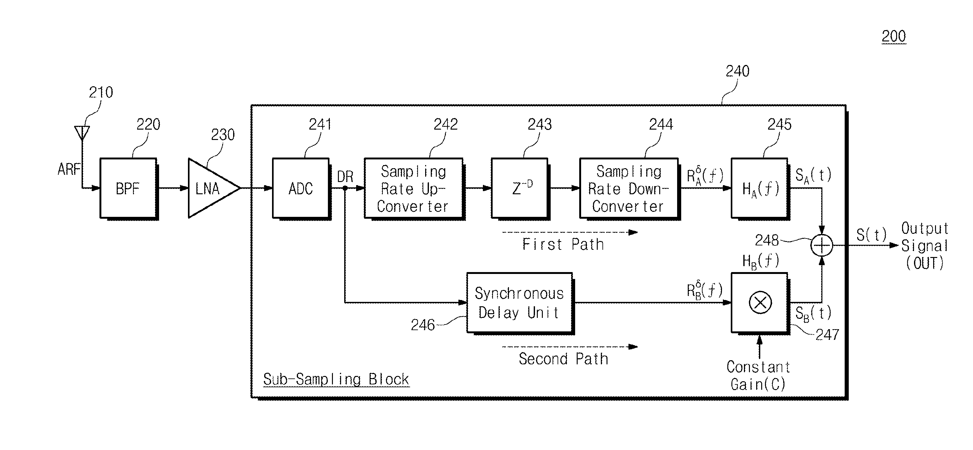
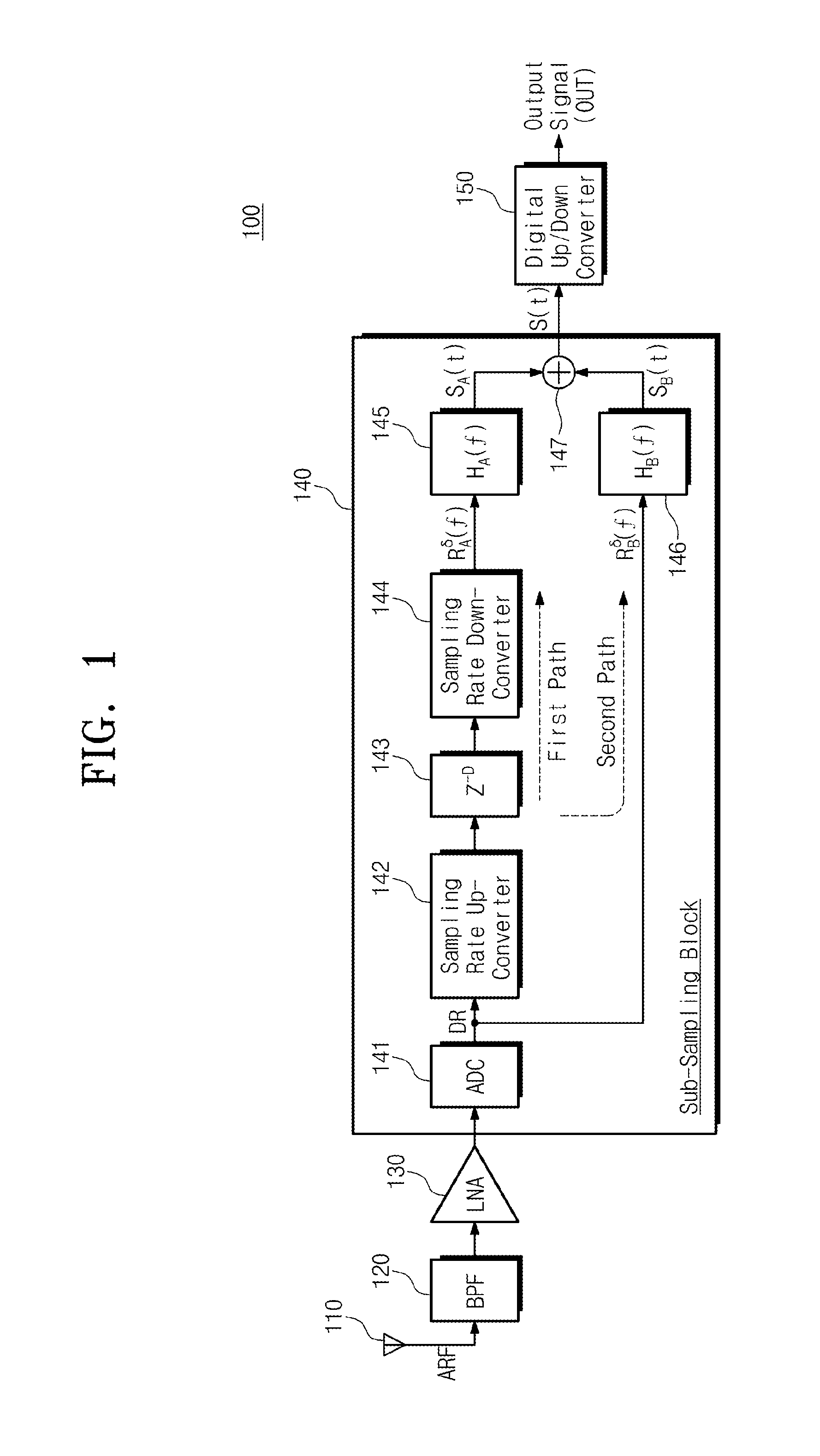
The present invention is a new type of sampling receiver that has several technical benefits. Firstly, it reduces the complexity of the hardware needed to perform the sampling. Secondly, it allows for flexible adjustment of the sampling rate. Thirdly, it effectively removes a problem called aliasing that occurs in the baseband signal. Finally, it prevents errors and imbalances in the size of the analog signal.

Problems solved by technology

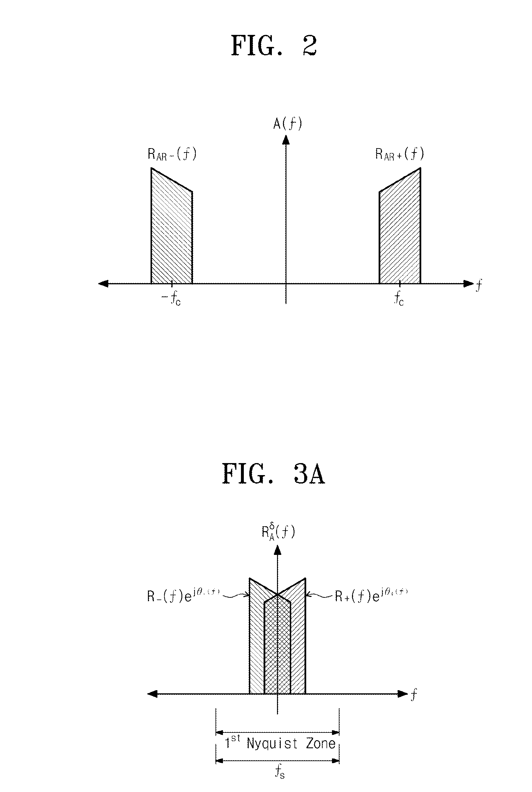
However, a typical sub-sampling receiver has a limitation in that it is possible to down-convert a received analog RF signal into the base-band signal in digital form only when a carrier frequency becomes a multiple of a sampling rate in receiving a single RF signal.
However, determining the sampling rate at which aliasing does not occur is very complicated and furthermore, there are many cases where there is no solution for the sampling rate at which the aliasing does not occur.
Thus, there is a limitation in receiving an RF signal located at any frequency band by using the typical sub-sampling receiver.
However, since a typical second-order band-pass sampling receiver uses two ADCs, it increases hardware complexity and has a serious performance degradation resulting from an analog time error between two signal paths and imbalance in an analog signal size.

Method used


Image

  • Sub-sampling receiver
  • Sub-sampling receiver
  • Sub-sampling receiver

Examples


Embodiment Construction

[0026]The above general descriptions and the following detailed descriptions all are exemplary for providing additional descriptions on the claimed invention. Therefore, the present invention is not limited embodiments to be described below but may be implemented in other forms. Exemplary embodiments introduced herein are provided to make disclosed contents thorough and complete and to sufficiently transfer the spirit of the present invention to a person skilled in the art.

[0027]The terms used herein are only used to describe specific embodiments and not intended to limit the present invention. The terms in singular form include the plural form unless otherwise specified. It should be understood that the terms “includes” or “has” indicate the presence of characteristics, numbers, steps, operations, components, parts or combinations thereof represented in the present disclosure but do not exclude the presence or addition of one or more other characteristics, numbers, steps, operation...


PUM


Abstract

Provided is a wireless signal receiver including: an analog-digital converter (ADC) converting an analog RF signal into a digital baseband signal; and a sub-sampling block dividing and processing the digital baseband signal into a first path signal and a second path signal, and extracting a complex baseband signal by using a relative sample delay difference between the first and second path signals, wherein the first path signal is a signal obtained by adjusting a sample delay and sampling rate of the digital baseband signal, and the second path signal is a signal obtained by filtering without adjusting the sampling rate of the digital baseband signal.

Description

CROSS-REFERENCE TO RELATED APPLICATIONS[0001]This U.S. non-provisional patent application claims priority under 35 U.S.C. §119 of Korean Patent Application Nos. 10-2013-0140987, filed on Nov. 19, 2013, and 10-2014-0141534, filed on Oct. 20, 2014, the entire contents of which are hereby incorporated by reference.BACKGROUND OF THE INVENTION[0002]The present invention disclosed herein relates to a communication system, and more particularly, to a sub-sampling receiver.[0003]With the miniaturization trend of a wireless communication system, needs for a next-generation wireless communication receiver having flexibility, adaptability and cognitivity are increasing. In order to satisfy these needs, there is a need for a technology to design a receiver of which the analog-to-digital converter (ADC) is as similar as possible to an antenna and which performs frequency conversion and demodulation functions by using a digital signal processor (DSP). As a next-generation wireless communication r...

Claims


Application Information

Patent Timeline
IPC IPC(8): H04L7/00H04L25/08
CPCH04L7/0087H04L25/08H04L7/0033H04L25/05H04B1/0021
Inventor SEO, SEOKKIM, JINUPLEE, SEUNG-HWAN
Owner ELECTRONICS & TELECOMM RES INST
Learn More